


20
Your company internal use only.
Copyright (C) Mitsubishi Electric Corporation.
NR-242UM-13LND0,13-WS
DISASSEMBLING PROCEDURES
●
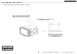
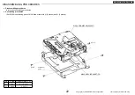
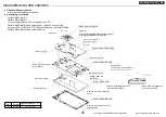
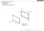
Disassembling procedures
In reverse of assembling procedures.
●
Assembling procedures
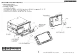
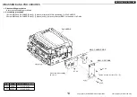
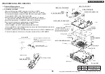
1.Assemble M011 to positioning A of M046.
* Assemble M011 so that a label becomes the upper part.
* Refer to permission load and the weight bearing of the fig. below for M011 handling.
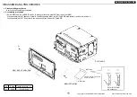
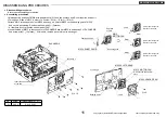
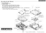
2.Assemble M046 (After work process1) to positioning B of M043, and screw with
Ⓐ
. (2 places)
* At this time, a lead be careful not to be caught .
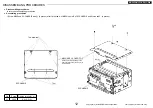
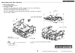
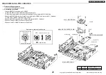
3.Assemble M060 to positioning C of M043, and screw with
Ⓐ
. (3 places)
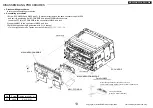
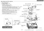
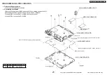
4.Connect lead A of M011 to connector B of M060.
5.Connect lead C of M043 to connector D of M060.
Load NG area
Permission load: To 1kgf
Handling possibility area
XY direction
exhaust outlet side NG
Lead C
Lead A
Positioning B
Positioning A
Connector B
Connector D
Ⓐ
x 2
Positioning C
A permission load and load domain
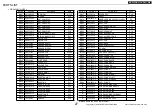
M043: ASSY-SLIDE
No.
Screw
Tighten torque(N
・m)
Ⓐ
2.6X6
0.4 +0.2/-0.1
Ⓐ
x 3
M046: ASSY-HOLDER-FAN-B
M011: MOTOR-FAN
M060:
ASSY-PCB-AUDIO-SUB


