


12 - 10
12. CC-Link CONNECTION (INTELLIGENT DEVICE STATION)
12.3 GOT Side Settings
12.3 GOT Side Settings
12.3.1
Setting communication
interface (Communication
settings)
Set the channel of the connected equipment.
1.
Select [Common]
[Controller Setting] from the
menu.
2.
The Controller Setting window is displayed. Select the
channel to be used from the list menu.
3.
Set the following items.
• Manufacturer: Mitsubishi
• Controller Type: Set according to the Controller
Type to be connected.
• I/F: Interface to be used
• Driver:CC-Link Ver2 (ID)
4.
The detailed setting is displayed after Manufacturer,
Controller Type, I/F, and Driver are set.
Make the settings according to the usage
environment.
12.3.2 Communication detail settings
Click the [OK] button when settings are completed.
POINT
POINT
POINT
The settings of connecting equipment can be
confirmed in [I/F Communication Setting].
For details, refer to the following.
1.1.2 I/F communication setting
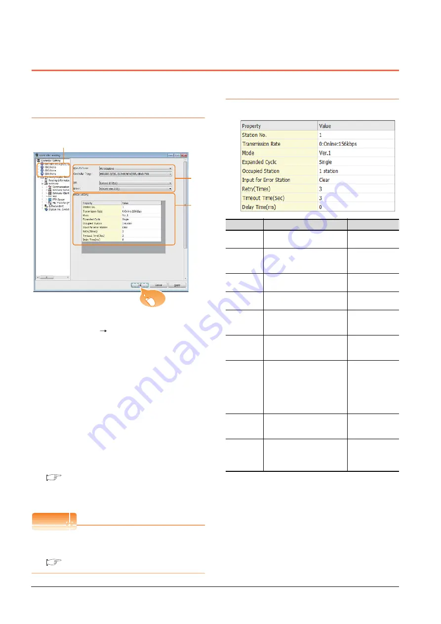
12.3.2
Communication detail settings
Make the settings according to the usage environment.
*1
Transmission speed settings
The following lists the transmission speed settings of the CC-
Link communication.
2.
3.
4.
Click!
Item
Description
Range
Station No.
Set the station No. of the GOT.
(Default: 1)
1 to 64
Transmission
Rate
*1
Set the transmission speed and
the mode of the GOT.
(Default: 0)
0 to E
Mode
Set the mode of CC-Link.
(Default: Ver.1)
Ver.1/Ver.2/
Additional/Offline
Expanded
Cyclic
Set the cyclic point expansion.
(Default: Single)
Single/Double/
Quadruple/Octuple
Occupied
Station
Set the number of stations
occupied by the GOT.
(Default: 1 Station)
1 Station/4 Stations
Input for Error
Station
Set Clear/Hold at an error
occurrence.
(Default: Clear)
Clear/Hold
Retry
Set the number of retries to be
performed when a communication
timeout occurs.
When no response is received
after retries, a communication
times out.
(Default: 3times)
0 to 5times
Timeout Time
Set the time period for a
communication to time out.
(Default: 3sec)
3 to 90sec
Delay Time
Set the delay time for reducing the
load of the network/destination
PLC.
(Default: 0ms)
0 to 300 (ms)
Summary of Contents for GOT2000 Series
Page 2: ......
Page 62: ...1 38 1 PREPARATORY PROCEDURES FOR MONITORING 1 6 Checking for Normal Monitoring ...
Page 64: ......
Page 80: ...2 16 2 DEVICE RANGE THAT CAN BE SET 2 6 MELSEC WS ...
Page 246: ...7 26 7 COMPUTER LINK CONNECTION 7 6 Precautions ...
Page 252: ...8 6 8 BUS CONNECTION 8 1 Connectable Model List ...
Page 256: ...8 10 8 BUS CONNECTION 8 2 System Configuration ...
Page 288: ...8 42 8 BUS CONNECTION 8 4 Precautions ...
Page 324: ...9 36 9 MELSECNET H CONNECTION PLC TO PLC NETWORK MELSECNET 10 CONNECTION PLC TO PLC NETWORK ...
Page 416: ......
Page 510: ...15 46 15 SERVO AMPLIFIER CONNECTION 15 7 Precautions ...
Page 518: ...16 8 16 ROBOT CONTROLLER CONNECTION 16 6 Precautions ...
Page 540: ...17 22 17 CNC CONNECTION 17 7 Precautions ...
Page 541: ...MULTIPLE GOT CONNECTIONS 18 GOT MULTI DROP CONNECTION 18 1 ...
Page 542: ......
Page 567: ...MULTI CHANNEL FUNCTION 19 MULTI CHANNEL FUNCTION 19 1 ...
Page 568: ......
Page 599: ...FA TRANSPARENT FUNCTION 20 FA TRANSPARENT FUNCTION 20 1 ...
Page 600: ......
Page 668: ...20 68 20 FA TRANSPARENT FUNCTION 20 7 Precautions ...
Page 670: ...REVISIONS 2 ...
Page 673: ......


