Mitsubishi FX-1PG User Manual Download Page 52

9.4

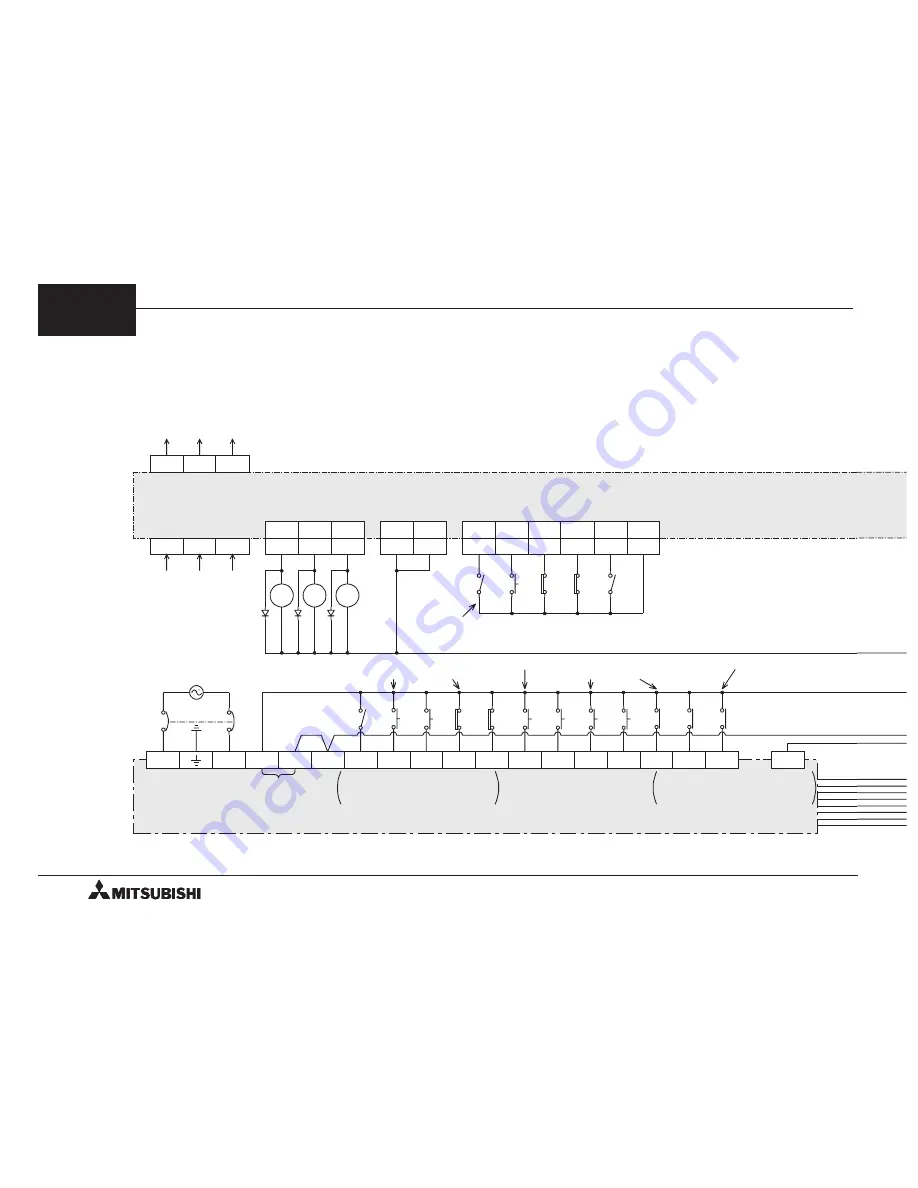
Example of External Connection (MR-J Servo Amplifier)

RD

24

PF

25

LSP

LSN

Forward

limit

Reverse
limit

30

31

SON

28

SG

13,14

R

S

U

V

W

To servo motor

RA1

RA2

MR-J
sermo amplifier

Servo

ON

Parameter Pr1 is set to
"position servo".

From three-phase

power supply

*2

ALM

27

RA3

T

VDD

VIN

35,36

34

RES

Alarm

reset

29

TL

Torque
restriction

33

*2

Rating: 3,000 r/min (MR-J10A ~ 60A)

2,000 r/min (MR-J100A ~ 350A)

SG

FX

,

FX

2C,

FX

2N

Series PC

X10

X11

X12

Positioning

completed

Servo failure

*2

RUN terminal is not provided
in FX

2N

, so this wiring is not

required in FX

2N

.

RA2 RA3

SG terminal is not provided in
FX

2N

, so this wiring is not

required in FX

2N

.

L

N

24V

RUN

X0

X1

X2

X3

X4

X5

X6

X7

STOP

RUN

Error
reset

Forward

limit Reverse

limit

JOG+

JOG-

Home

position

Start

S/S

0V

Sensor
power supply
24V DC

RA1

Servo

ready

9

FX-1PG/FX

2N

-1PG PULSE GENERATOR UNIT

EXTERNAL CONNECTION EXAMPLES

9-7

Summary of Contents for FX-1PG

Page 1: ...USER S MANUAL FX 1PG FX2N 1PG PULSE GENERATOR UNIT...

Page 2: ...tion can be found in the FX PROGRAMMING MANUAL II FX FX2N series hardware manuals If in doubt at any stage of the installation of FX 1PG FX2N 1PG pulse generator unit always consult a professional ele...

Page 3: ...FX 1PG FX2N 1PG PULSE GENERATOR UNIT USER S MANUAL FX 1PG FX2N 1PG PULSE GENERATOR UNIT Manual number JY992D65301 Manual revision E Date April 2003...

Page 4: ...with regards to automated equipment b Any commissioning or service engineer must be of a competent nature trained and qualified to the local and national standards required to fulfill that job These e...

Page 5: ...h of the symbols used will now be listed with a brief description of its meaning Hardware Warnings 1 Indicates that the identified danger WILL cause physical and property damage 2 Indicates that the i...

Page 6: ...etting 5 3 5 3 Speed Data and Position Data 5 6 5 4 Position Data Home Position and Current Position 5 9 5 5 Operation Command 5 10 5 6 Status and Error Codes 5 13 6 OUTLINE OF OPERATION MODES 6 1 6 1...

Page 7: ...ruction 7 1 8 I O SPECIFICATIONS 8 1 8 1 I O Specifications 8 1 9 EXTERNAL CONNECTION EXAMPLES 9 1 9 1 Example of Connection Between FX 1PG and Stepper Motor 9 1 9 2 Example of Connection Between FX2N...

Page 8: ...MEMO FX 1PG FX2N 1PG PULSE GENERATOR UNIT vi...

Page 9: ...The PGU provides connection terminals for positioning operations that require high velocity responses as well as those used for pulse train outputs Other general I O operations are controlled via the...

Page 10: ...xtension block The PGU can be installed using a DIN rail DIN 46277 Width 35 mm or directly installed using M4 screws For the details refer to the handy manual packed together with the main unit STOP D...

Page 11: ...er extension block The PGU can be installed using a DIN rail DIN 46277 Width 35 mm or directly installed using M4 screws For the details refer to the handy manual packed together with the main unit PO...

Page 12: ...5 V is supplied from PC STOP Lighted when stop command is entered Lighted by either STOP terminal or BFM 25 b1 DOG Lighted when DOG input is entered PG0 Lighted when zero point signal is entered FP F...

Page 13: ...VH Power terminal for pulse output supplied from servo amplifier or external unit 24V DC 10 Current consumption 15 mA VL Power terminal for pulse output supplied from servo amplifier or external unit...

Page 14: ...mental specifications The environmental specifications are equivalent to those of the main unit of the FX PC For the details refer to the handy manual packed together with the main unit 4 FX 1PG FX2N...

Page 15: ...cted among pulse m mdeg and 10 4 inch Multiplication of 100 101 102 or 103 can be set for position data Pulse output format Forward FP and reverse RP pulse or pulse PLS with direction DIR can be selec...

Page 16: ...mber of zero point signals for home position return N 0 to 32 767 PLS 14 13 Home position HP 0 to 999 999 2 15 Acceleration deceleration time Ta 50 to 5 000 ms 16 Reserved 18 17 Set position I P I 0 t...

Page 17: ...100 000 Hz Initial value 0 Hz Initial value 10 000 Hz Initial value 50 000 Hz Initial value 1 000 Hz Initial value 10 PLS Initial value 0 Initial value 100 ms Initial value 0 R W Initial value 10 Hz...

Page 18: ...it among m R mdeg R and 10 4inch R suitable to the application The BFMs 2 and 1 are not required to be set when the motor system of units described later is selected BFM 3 Parameters b0 to b15 Set bit...

Page 19: ...nt position CP value increases with a forward pulse FP When b9 1 The current position CP value decreases with a forward pulse FP This bit is used for the initial setting The rotation direction is not...

Page 20: ...maining distance is restarted when the restart command is given The Jog drive begins again when the stop command is turned off from turning on when the Jog command has been turned on However if any BF...

Page 21: ...to 153 000 This is the speed for manual forward reverse JOG JOG Set a value between the bias speed Vbia and the maximum speed Vmax BFMs 10 and 9 Home position return speed high speed VRT Motor system...

Page 22: ...rotation direction is determined in accordance with the absolute value of the set position based on the current position BFMs 26 and 27 When the relative position is used the rotation direction is det...

Page 23: ...s and the machine system of units They are automatically converted each other Speed command A 104 cm min 10deg min inch min B1 B2 or B3 Speed command Hz x 60 A indicates the pulse rate B1 to B3 indica...

Page 24: ...combined system of units When the pulse rate of the BFM 0 2 1 is supposed the pulse rate as A the feedrate as B and the relative travel distance as C the value C A B indicates the pulse quantity whic...

Page 25: ...for 300 ms or more continuous forward pulses are generated b5 When b5 1 JOG operation When b5 continues to be 1 for less than 300 ms one reverse pulse is generated When b5 continues to be 1 for 300 m...

Page 26: ...X001 X002 X003 X004 X005 X006 Start X007 M8000 M 2 M 3 M 4 M 5 M 6 M 7 M 8 M 9 M 1 M 0 M 10 M 11 M 12 M8000 RUN monitor Error reset M15 M 0 BFM 25 b15 b 0 Stop command Forward pulse stop Reverse pulse...

Page 27: ...If two or more of them are turned on operation is disabled See Section 6 4 As the general start command create an appropriate sequence using the input X007 to drive the M8 to M12 See Section 9 1 The...

Page 28: ...m b2 home position return completed only in the BFM 28 is reset and rewritten to 0 b3 When b3 0 STOP input OFF When b3 1 STOP input ON b4 When b4 0 DOG input OFF When b4 1 DOG input ON b5 When b5 0 PG...

Page 29: ...SY Reading of status information When a drive amplifier for a stepper motor without the positioning completed output is used this signal can be used for recognition of positioning completed and the ne...

Page 30: ...OO indicates the corresponding BFM No For example 172 indicates that the BFMs 18 and 17 are set to 0 OO3 Setting range is incorrect OO indicates the corresponding BFM No For example 043 indicates tha...

Page 31: ...MEMO 5 FX 1PG FX2N 1PG PULSE GENERATOR UNIT BFM LIST 5 16...

Page 32: ...tart command is received the motor makes the machine return to the home position When returning to the home position is completed the home position HP BFMs 14 and 13 value is written to the current po...

Page 33: ...same point which will affect the repeatability of the home position return operation On the other hand the servo amplifier outputs one zero point signal PG0 Z phase signal 0P for each revolution of th...

Page 34: ...o 1 so that the motor is stopped at the first zero point signal PG0 When the operation is stopped the deviation counter clear signal CLR of the servo amplifier is output The home position BFMs 14 and...

Page 35: ...omatically go back using these limit switches See Section 6 1 4 Dispersion in the point at which the dog starts to be in contact with the dog switch is required to be adjusted so that the dog switch i...

Page 36: ...ned on the pulse output is immediately stopped BFM 25 b3 ON At this time the clear signal is also output When the stepper motor is used When the stepper motor is used rigid attention should be paid to...

Page 37: ...single speed positioning operation command is received the motor performs the following operation The interrupt command is connected to the DOG input in the PGU When the start command is received the...

Page 38: ...The PGU does not control the pulse quantity and positioning is performed by the two step speed technique When the start command is received the motor performs positioning at the operating speed V I BF...

Page 39: ...ed operation is performed When b12 is set to 0 pulse output is stopped The pulse output does not stop even if 0 is written in BFM 20 19 As for the parameter BFM 3 only b1 and b0 system of units and b8...

Page 40: ...uch as b4 to b6 and b8 to b12 are turned on simultaneously in the operation command BFM 25 any operation is not executed If an other mode input is turned on while operation is being performed in any m...

Page 41: ...0 1 When normally open contacts are used The input connection diagram shown below indicates the case where the BFM 3 b 12 and b14 are set to 0 and normally open contacts a contacts are used Input swit...

Page 42: ...switches on the PC When b2 and b3 of the BFM 25 are driven by these signals pulse output is immediate stopped and the counter clear output CLR is generated See Section 8 4 Evade from the state of the...

Page 43: ...igh speed O 11 Hime position return speed creep speed 12 Number of zero point signals for home position return 14 13 Home position 15 Acceleration deceleration time O O O O O O 16 Reserved 18 17 Set p...

Page 44: ...ad address of transfer destination T C D KnX KnM KnY KnS V Z K and H can be specified and element No can be coupled with an index When X010 and X011 are turned off transfer is not performed and data i...

Page 45: ...A 5 to 15V Current consumption 20 mA from servo amplifier or external power supply To pull up resistor VH or VL 100k Hz pulse output 5 to 24V DC 20 mA or less 100k Hz pulse output 5 to 24V DC 20 mA or...

Page 46: ...hen there is no home position sensor At this time when the dog input operates the motor stops at once Make the home position return speed low speed very because it does not destroy the machine Extensi...

Page 47: ...CLR PG0 PG0 CCW CCW CW CW AC100AC100 FG 5V DC DOG STOP 100V AC power supply 1 1 FX 1PG e 220 220 Stepper motor Grounding resister 100 or less Class 3 2 Home position sensor 9 FX 1PG FX2N 1PG PULSE GE...

Page 48: ...rt 3 3k FX2N Series PC S S 0V Sensor power supply 24V DC 1 The number of counts of zero signals is adjusted to 0 when there is no home position sensor At this time when the dog input operates the moto...

Page 49: ...PG0 PG0 CCW CCW CW CW AC100AC100 FG 5V DC DOG STOP 100V AC power supply FX2N 1PG 220 220 Stepper motor Grounding resister 100 or less Class 3 1 Home position sensor 9 FX 1PG FX2N 1PG PULSE GENERATOR U...

Page 50: ...Forward limit 15 14 SON 17 SG 12 L1 L2 U V W To servo motor RA1 RA2 2 MR C A MR C A1 Servo amplifier Servo ON Parameter Pr16 is set to position servo MR C A MR C A1 Single phase 200V AC Single phase 1...

Page 51: ...ect the VL terminal when the external power supply is 5V DC FX2N 1PG Connect the VIN terminal SG S S DOG STOP 4 FP COM0 RP COM1 CLR PG0 PG0 SG NP PP SD OP V24 LSD STOP 11 5 7 9 OPC V24 V 19 20 1 SG te...

Page 52: ...33 2 Rating 3 000 r min MR J10A 60A 2 000 r min MR J100A 350A SG FX FX2C FX2N Series PC X10 X11 X12 Positioning completed Servo failure 2 RUN terminal is not provided in FX2N so this wiring is not req...

Page 53: ...G Connect the VIN terminal 2 Pin No for the case where Pr9 of the servo amplifier is set to 042 SG S S DOG STOP 1 FP COM0 RP COM1 CLR PG0 PG0 SG NP PP SD OP P15R LSD STOP 18 15 22 20 OPC 23 SG termina...

Page 54: ...striction 9 2 EGM Emergency stop 15 CON1A CON1B 2 2 SG FX FX2C FX2N Series PC X10 X11 X12 Positioning completed Servo failure RUN terminal is not provided in FX2N so this wiring is not required in FX2...

Page 55: ...Pin No can be modified using the extension parameter The example below shows the case where the initial value is set SG S S DOG STOP 1 FP COM0 RP COM1 CLR PG0 PG0 SG NP PP SD OP P15R LSD STOP Plate 1...

Page 56: ...ue restriction 13 EMG Emergency stop 46 SG FX FX2C FX2N Series PC X10 X11 X12 Positioning completed Servo failure RUN terminal is not provided in FX2N so this wiring is not required in FX2N RA2 RA3 SG...

Page 57: ...power supply See Section 8 1 FX2N 1PG Connect the VIN terminal SG S S DOG STOP 1 FP COM0 RP COM1 CLR PG0 PG0 SG NP1 PP1 SD OP P15R LSD STOP 50 47 19 18 SG terminal is not provided in FX2N so this wir...

Page 58: ...r reverse button is pressed and held the motor is driven forward or in reverse Jog operation 3 The value of the motor advances 10000 mm according to the automatic drive start instruction After wards Y...

Page 59: ...ulses Outputs to PP of the servo amplifier X004 Jog operation X005 Jog operation RP Reverse pulses Outputs to NP of the servo amplifier X006 Home position return start X007 Automatic drive start Singl...

Page 60: ...rse pulse stop M3 b14 STOP input polarity 0 Stops because of turning on b4 JOG M4 b15 STOP input mode 0 The remainder distance drive b5 JOG M5 5 4 Maximum speed 50000 b6 Home position return start M6...

Page 61: ...ording to the parameter Control mode Position control Electronic gear CMX CDV 1 1 Specified pulse selection Forward reverse pulse Negative true logic Set other items according to the usage 10 FX 1PG F...

Page 62: ...K 1 D FNC 79 TO K 0 K 15 K 100 K 1 FNC 79 TO K 0 K 12 K 10 K 1 Writing of pulse rate Writing of feed rate Writing of parameters Writing of maximun speed Writing of bias speed Writing of JOG speed Wri...

Page 63: ...10 K10000 Current value 10000 M8002 FNC 79 TO K 0 K 17 K10000 K 1 D FNC 79 TO K 0 K 17 K 10000 K 1 D X000 X001 X002 X004 X005 X006 M8000 M 7 M 6 M 5 M 4 M 1 M 2 M 3 M 0 Error reset STOP Forward pulse...

Page 64: ...K0 M33 ON D11 D10 K0 M34 ON D11 D10 K0 M35 ON M28 M31 T0 Y000 K20 Stop for 2 seconds Stand by display END M8000 FNC 79 TO K 0 K 25 K4M0 K 1 Positioning completed flag D11 D10 K10000 Current value 100...

Page 65: ...15 save the standard data and the BFMs 17 to 24 save the operation data For the data to be set see Section 6 6 Error indication LED indication The PGU panel has the following LEDs Power indication Th...

Page 66: ...MEMO 11 FX 1PG FX2N 1PG PULSE GENERATOR UNIT DIAGNOSTICS 11 2...

Page 67: ...mples and diagrams shown in this manual are intended only as an aid to understanding the text not to guarantee operation Mitsubishi Electric will accept no responsibility for actual use of the product...

Page 68: ...UCHI TOKYO 100 8310 HIMEJI WORKS 840 CHIYODA CHO HIMEJI JAPAN JY992D65301E MEE Effective Apr 2003 Specifications are subuject tochange without notice USER S MANUAL FX 1PG FX2N 1PG PULSE GENERATOR UNIT...

Reviews: