


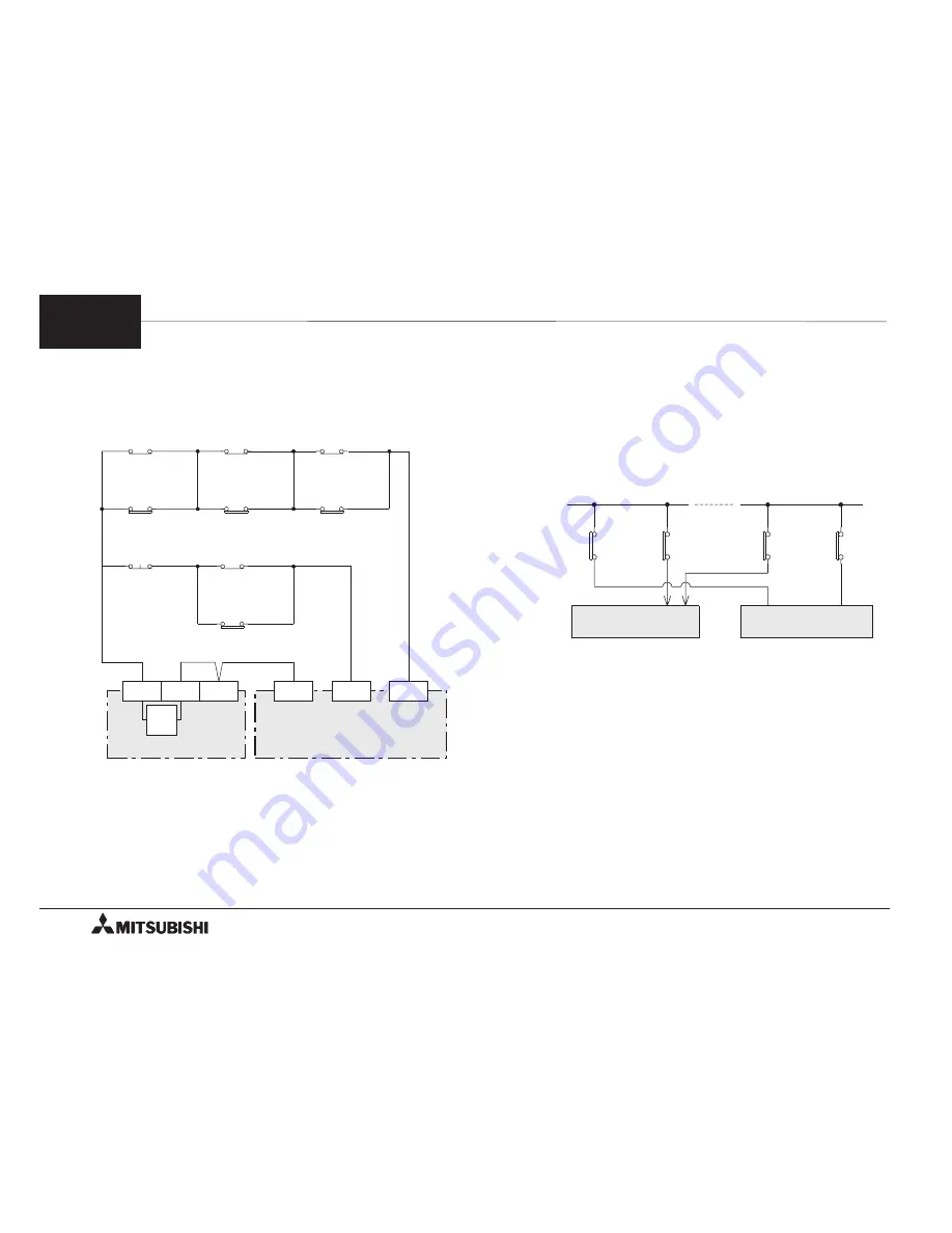
< When normally closed contacts are used >
The input connection diagram shown below indicates
thecasewheretheBFM #3 b 12 and b14 areset to 1
and normally closed contacts (b-contacts) are used.
Input switches SW1 to SW3 are selected in accordance
with thetypeof operation.
•
To assure safety, provide limit switches for
detecting the forward and reverse limits on the
servo amplifier also. (See Section 8.4.)
Make sure so that the limit switches on the PC
are actuated simultaneously with or a little earlier
than thelimit switches on theservo amplifier.
•
Because a drive amplifier for a stepper motor does
not have these terminals, make sure to provide
limit switches on the PC.
•
When b2 and b3 of the BFM #25 are driven by
these signals, pulse output is immediate stopped
and the counter clear output CLR is generated.
(See Section 8.4.)
•
Evadefrom thestateof thepulseoutput stop by
Jog in theoppositedirection when forward pulse
stop (BFM #25 b2) or reverse pulse stop (BFM
#25 b3) is turned on.
•
Becausethecounter clear output CLR is genarated,
theforward pulsestop and thereversepulsestop
cannot beused as a stop and homeposition.
PC
Forward
limit
Forward
limit
Servo amplifier
LSP
LSN
Reverse
limit
Reverse
limit
24V
SW1
Home position
return
LSD
Near point
signal
SW2
Interrupt
single-speed
LSI
INTERRUPT
input
SW3
External
command
LS1
Deceleration
start
STOP
input
SW3
External
command
LS2
Stop point
0V
S/S
STOP
DOG
PGU
PC
S/S
24V
DC
6
FX-1PG/FX
2N
-1PG PULSE GENERATOR UNIT
OUTLINE OF OPERATION MODES
6-11


