background image

INSTALLATION OR REMOVAL SERVICE POINTS

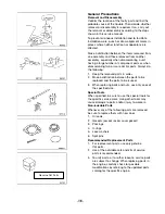
Install the oil pump screen.

• If removed, replace the oil pump screen. The oil

pump screen must have a good press fit into the
oil pump body.

• Mount the oil pump in a soft jawed vise.
• Apply sealer to the end of the pipe.
• Use the (J 21882) and a soft-faced hammer to

tap the oil pump screen into the pump body. The
screen must align parallel with the bottom of the
oil pan when it is installed.

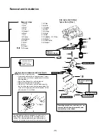
Removal steps

1. Plug
2. Nut
3. Bolt
4. Pan
5. Gasket
6. Bolt
7. Pin
8. Pump
9. Retainer

10. Shaft
11. Bolt
12. Pin
13. Cover
14. Screen

4

5

1

2

3

15. Plug
16. Valve
17. Spring
18. Filter
19. Fitting
20. Valve
21. Bolt
22. Adapter - Oil Filter
23. Gasket
24. Connector
25. Gasket

22

20

19

18

25

24

21

10

9

8

14

13

12 

11

7

6

17

16

15

23

Lubricate all inter-
nal parts with
engine oil during

Unit: kgf-m (lb-ft) [N-m]
*kgf-m (lb-in.) [N-m]

T = 1.22 (106) [12]

Removal and Installation

A

A

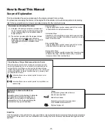
Operating procedures, cautions, etc., on
removal, installation, disassembly and
reassembly are described.

Denotes tightening
torque.

This alphabetical letter corresponds to a part that is
indentified in the drawing on the first page of each
section. The letter appears during an explanation of
removal, installation, disassembly or reassembly steps. 

Denotes 
nonreusable part.

-III-

N

N

N

T = 9.14 (66) [90]

T = 2.08  (15) [20]

T = 2.49  (18) [25]

T = 2.49 (18) [25]

T = 2.49 (18) [25]

J 21882

Summary of Contents for FG35-FG50

Page 1: ...Service Manual 99789 74120 For use with the FGC35K FGC70K FG35 FG50 FG40K FG50K Chassis Service Manuals GM 4 3L G6 Gasoline Engine 003103 up...

Page 2: ...reserves the right to change specifications or design without notice and without incurring obligation Whenever a question arises regarding this engine or this manual consult your Cat lift truck deale...

Page 3: ...automatic transmission fluid or air conditioner compressor oil Engine oil or gear oil Symbols for Lubrication Sealants and Adhesives Information concerning the locations for lubrication and applicatio...

Page 4: ...15 Plug 16 Valve 17 Spring 18 Filter 19 Fitting 20 Valve 21 Bolt 22 Adapter Oil Filter 23 Gasket 24 Connector 25 Gasket 22 20 19 18 25 24 21 10 9 8 14 13 12 11 7 6 17 16 15 23 Lubricate all inter nal...

Page 5: ...ck unless you have read and understand the instructions in the OPERATOR S MANUAL Improper truck operation is dangerous and could result in injury or death 5 Use steps and grab handles if applicable wh...

Page 6: ...ard or paper to locate pin hole leaks 19 Tighten connections to the correct torque Make sure all heat shields clamps and guards are installed correctly to avoid excessive heat vibration or rubbing aga...

Page 7: ...necting rod cap Crankshaft bearings and connecting rod bearings Engine camshaft and valve lifters Valve lifters valve rocker arms and valve rocker arm supports Valve to valve guide Valve spring to cyl...

Page 8: ...emoved for service they should be retained in order At the time of installation they should be installed in the same locations and with the same mating surface as when removed 1 Wash all parts except...

Page 9: ...parts in order 2 Make a distinction between the parts to be replaced and the parts to be reused 3 When replacing bolts and nuts use only ones of the specified size Special Tools When specified be sur...

Page 10: ...disconnecting a connector do not pull the harness Hold the halves of the connector to separate them from each other When disconnecting a lock type connector push the lock lever s in the direction s s...

Page 11: ...bber hoses or tubes otherwise the rubber is likely to deteriorate Greasing During assembly or installation coat the designated surfaces with the specified grease or oil Cooperation When two or more pe...

Page 12: ...epairing the Leak 23 Engine Lubrication 25 Intake Manifold 29 Intake Manifold Removal 30 Intake Manifold Installation 31 Exhaust Manifold 33 Oil Level Indicator and Tube Removal 34 Exhaust Manifold an...

Page 13: ...on 86 Crankshaft Flywheel Rear Seal and Bearings 89 Engine Flywheel Removal 90 Crankshaft Rear Oil Seal and Housing Removal 90 Crankshaft and Bearings Removal 91 Crankshaft and Bearings Clean and Insp...

Page 14: ...165 Alternator 167 Accessory Drive Belt Replacement 168 Starter Motor 169 Starter Motor Testing 170 Troubleshooting 170 Fuel System Gasoline Units built before 01 01 2004 173 Fuel Pump and Fuel Hose U...

Page 15: ...er troubles Engine Set Up and Testing After overhaul the engine must be tested before it is installed in the truck If a suitable test stand is not available the following procedures can be used after...

Page 16: ...BUY NOW Then Instant Download the Complete Manual Thank you very much...

Reviews: