


MITSUBISHI ELECTRIC 7011A SERIES UPS
MITSUBISHI
ELECTRIC
7011A SERIES UPS
OWNERS / TECHNICAL MANUAL
Page Number:
1-6
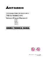
FIGURE 1.2
Single Line Diagram - Bypass Operation. Load fed through static bypass line.
Referring to Figure 1.2, the Internal Static Bypass line is a hard-wired line which supplies the
critical load with unconditioned input power. The purpose of this line is to route power to the
critical load while the UPS module is de-energized (converter and inverter), and during Start-up
before the system is fully operational.
The internal control system determines the operation of the two paths, with the load powered
from the inverter being the normal operation.
Referring to Figure 1.3, if the input power is interrupted, the battery will immediately supply the
DC power required by the Inverter to maintain continuous AC power to the load. A fully charged
battery will provide power for the specified time at the rated load, or longer at reduced load.
When power is restored after a low battery shutdown, the Converter automatically restarts
operation, recharges the batteries and the Inverter is automatically restarted without operator
intervention. The load is assumed by the inverter automatically without operator intervention.
In the event of a power failure, the Converter will de-energize and the batteries will discharge into
the Inverter and maintain power to the critical load until a) the battery capacity expires and the
inverter turns off, or b) input power is restored after which the converter will power the inverter
and simultaneously recharge the batteries. Figure 1.3 illustrates the flow diagram during battery
operation.
Maintenance
Bypass Switch
FB
BATTERY
CB2
Static Transfer
Switch
Power Flow
Not in Use
Output
CB1
FI
FO
CONVERTER
INVERTER
UPS Cabinet
52CS
AC input
CB
User supplied
MCCB


