


-
267
-
T
o indoor
unit
*
*
0
20
40
60
80
100
120
140
160
180
200
0
2
04
0
6
08
0
1
0
0
1
2
0
1
4
0
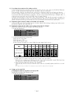
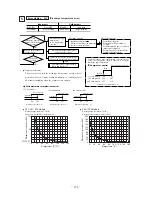
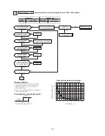
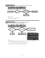
T
emper
ature-resistance char
acter
istics of
A/F ther
mistor (Tho-AF)
Thermistor resistance (k
Ω
)
L
L1i
Ni
CNW2
CNF
AN1
CNI1
CNI3
CNI2
CNI4
CNIP
CNA2
CNA1
CNW
LED2
(Red)
FM01
LED1
(Green)
L1o
No
TB
7
TB
TB
Red
Red
White
Red
White
Blue
White
White
Blue
Y
ello
w
/Green
F(30A)
N
E
1
2
3
E1
E2
2
1
CT
Noise filter
A/F ther
mistor
DM
CM
~
~
+
+
–
–
CNA
CT1
Control PCB
In
v
er
ter PCB
TB
8
TB
9
LED1
(Y
ello
w)
TB
2
TB
1
TB1
0
TB1
1
TB
6
TB
5
A/F Module
PN
2
L1
L2
+
–
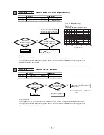
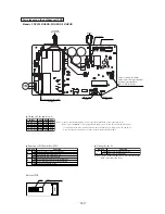
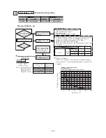
Po
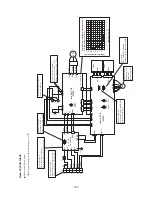
wer supply check:
Measure the po
wer supply L1,N
(It is normal if it is
A
C220/240V)
*
Noise f
ilter check:
There should be continuity
.
There should be no shorts between phases.
T
emper
ature (˚C)
DC280 ~ 373V
DC280 ~ 373V
Fuse check:
There should be continuity
.
When the outdoor
unit f
an motor is
abnormal:
(Refer to page 280)
Capacitor check:
Check for anomaly in appearance
such as damage, swelling, etc.
LED 1 (Y
ello
w) Check
Flashing 1 time:
Current cut (Po
wer transistor o
v
ercurrent)
• Compressor wiring short circuit
• In
v
erter PCB f
ailure
• Po
wer transistor f
ailure
Flashing 2 times:
In
v
erter PCB anomalous
• In
v
erter PCB f
ailure
Flashing 3 times:
Mounting and dismounting anomaly
• Compressor f
ailure
• In
v
erter PCB f
ailure
Flashing 4 times:
Compressor starting f
ailure
• Compressor f
ailure
• In
v
erter PCB f
ailure
• Po
wer transistor f
ailure
Flashing 5 times:
Current cut f
ailure
• In
v
erter PCB anomalous
Lighting:
Communications between in
v
erter and outdoor unit anomalous.
• Connectors CN1-1, 2, 3, 4 are disconnected or there is
a disconnection
between connectors.
• Outdoor unit control PCB anomalous.
• In
v
erter PCB anomalous.
Light continuously: Normal
DC Reactor continuity Check:
Max25m
Ω
Check the po
wer transistor
module if there is short, open, or
breakdo
wn on the elements
LED1(Green) check:
If it flashes, the microcomputer
operates normaly
.
• If it is of
f, check if CNI1 connector is connected properly
.
The po
wer is supplied by the in
v
erter PCB through CM
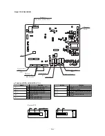
Models FDCV
A402~602HENAR
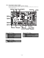
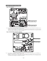
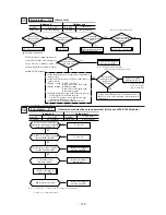
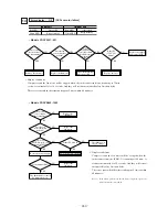
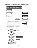
Outdoor unit check points
Check items with the *mark when the po
wer is ON.
Summary of Contents for FDCVA1002HESAR
Page 107: ... 106 60 17 150 b Wireless remote controller Unit mm ...
Page 119: ... 118 Model FDCVA1002HESAR Polar white ...
Page 133: ......