


-
240
-
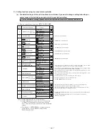
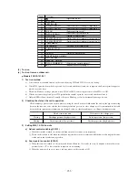
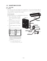
Section
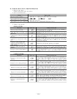
Display section
Error code of remote controller
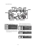
Inspection LED (red) of indoor unit PCB
Inspection LED (red) of outdoor unit PCB
• Displays the error of higher priority (When plural errors are persisting)
• Displays the present errors.
(When a new error has occurred after the former error was reset.)
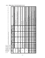
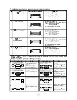
Error detail
Error code
Timing of error detection
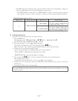
Wrong connection between the indoor and
outdoor units.
“ WAIT ”
When it is detected at any time after the power is supplied.
Broken wire of heat exchanger thermistor
Drain error (float switch motion)
When the communication between the indoor unit and the remote controller is
interrupted for 2 minutes after it tries to communicate once or more times
after the power is supplied.
When the floating switch is activated for more than 3 seconds continuously
30 seconds after the power is turned ON.
When the communication between the indoor unit and the outdoor unit is
never done.
When the communication between the indoor unit and the outdoor unit is
interrupted for 2 minutes after it tries to communicate once or more times
after the power is supplied.
When an input temperature of –50 ˚C or lower is measured by the return air
thermistor for 5 seconds or longer within 60 minutes after the first detection.
When an input temperature of –50 ˚C or lower is measured by the heat
exchanger thermistor for 5 seconds or longer within 60 minutes after the first
detection.
Transmission error of remote controller and
indoor unit
Transmission error between indoor/outdoor
units
The number of connected indoor units
exceeds the connection limit (when
multiple units are control led by a single
remote controller).
Broken wire of indoor unit return air
thermistor
···········
···········
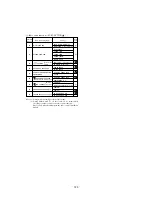
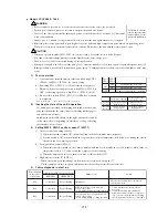
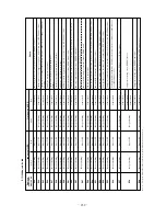
Error detail
Error code
Timing of error detection
Broken wire of heat exchanger thermister
Broken wire of discharge pipe thermistor
Broken wire of suction pipe thermistor
Broken wire of low pressure sensor
Broken wire of ambient air temperature
thermistor
Broken wire of under the under-dome
thermistor
When a thermistor input temperature of –30 ˚C or lower is measured for 5
seconds or longer 3 times within 40 minutes after the 1st detection in done
between 2 minutes and 2 minutes 20 seconds after compressor operation
starts.
When a thermistor input temperature of –50 ˚C or lower is measured for 5
seconds or longer 3 times within 40 minutes after the 1st detection in done
between 2 minutes and 2 minutes 20 seconds after compressor operation
starts.
When a thermistor input temperature of –10 ˚C or lower is measured for 5
seconds or longer 3 times within 40 minutes after the 1st detection in done
between 10 minutes and 10 minutes 20 seconds after compressor operation
starts.
When a thermistor input temperature of –50 ˚C or lower is measured for 5
seconds or longer 3 times within 40 minutes after the 1st detection in done
between 10 minutes and 10 minutes 20 seconds after compressor operation
starts.
When a sensor is OV or lower or 3.49V or higher continously for 5 seconds or
longer 3 times within 40 minutes after the 1st detection in done between 2
minutes and 2 minutes 20 seconds after compressor operation starts.
When the under-dome thermistor input temperature of –50 ˚C is measured for
5 seconds or longer 3 times within 40 minutes after the 1st detection in done
between 10 minutes and 10 minutes 20 seconds after compressor operation
starts.
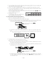
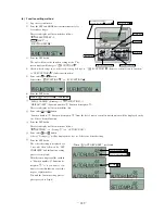
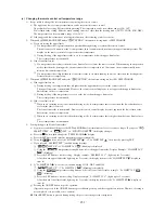
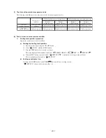
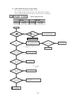
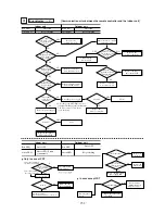
(b) Display sequence of error, inspection display lamp
1) In case an error occurs
Display corresponding to the error is shown.
2) In case several errors occur
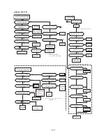
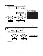
3) Timing of error detection
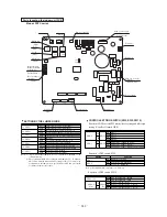
Indoor unit side.
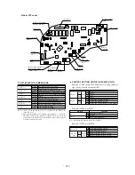
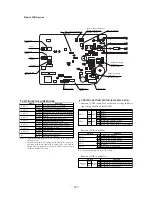
Outdoor unit side.
Summary of Contents for FDCVA1002HESAR
Page 107: ... 106 60 17 150 b Wireless remote controller Unit mm ...
Page 119: ... 118 Model FDCVA1002HESAR Polar white ...
Page 133: ......