Mitsubishi Heavy Industries 25ZMX-S Technical Manual Download Page 33

-


-

 '13 • SRK-T-144D

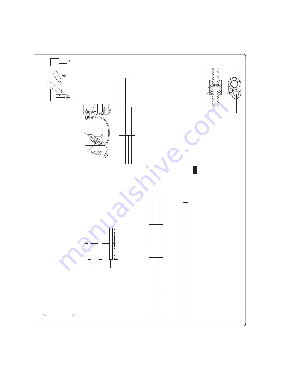
Wires for connecting indoor and outdoor units

Exterior tape

Gas piping

Insulation

Liquid piping

Band (procured locally)

Pipe cover (procured locally)

8) Heating and condensation prevention

5) Air tightness test

Gas side  service valve

Check joint

Pressurize

Close

Outdoor unit

Indoor unit

<Work flow>

6) Evacuation

Pay

attention

to

the

following

points

in

addition

to

the

above

for

the

R410A

and

compatible machines.

Air tightness test completed

Fill refrigerant

Vacuum gauge check

Vacuuming completed

Vacuuming begins

Although

outdoor

and

indoor

units

themselves

have

been

tested

for

air

tightness

at

the

factory,

check

the

connecting

pipes

afte

rthe

installation

work

for

air

tightness

from the service 

valve’s check joint equipped on the outdoor unit side. While conducting a test, keep the service valve shut all the time. a)

Raise

the

pressure

to

0.5MPa,

and

then

stop.

Leave

it

for

five

minutes

to

see

if

the

pressure

drops.

b)

Then

raise

the

pressure

to

1.5MPa,

and

stop.

Leave

it

for

five

more

minutes

to

see

if

the

pressure

drops.

c)

Then

raise

the

pressure

to

the

specified

level

(4.15MPa),

and

record

the

ambient

temperature

and

the

pressure.

d)

If

no

pressure

drop

is

observed

with

an

installation

pressurized

to

the

specified

level

and

left

for

about

one

day,

it

is

ac

ceptable.

When

the

ambient

temperature

fall

1

o

C,

the

pressure

also

fall

approximately

0.01MPa.

The

pressure,

if

changed,

should

be

compensated

for.

e)

If

a

pressure

drop

is

observed

in

checking

e)

and

a)

d),

a

leak

exists

somewhere.

Find

a

leak

by

applying

bubble

test

liqu

id

to

welded

parts

and

flare

joints

and

repair

it.

After

repair,

conduct

an

air

tightness

test

again.

In

conducting

an

air

tightness

test,

use

nitrogen

gas

and

pressurize

the

system

with

nitrogen

gas

from

the

gas

side.

Do

not

use

a

medium

other

than

nitrogen

gas

under

any

circumstances.

To

prevent

a

different

oil

from

entering,

assign

dedicated

tools,

etc.

to

each

refrigerant

type.

Under

no

circumstances

must

a

gauge

manifold

and

a

charge

hose

in

particular

be

shared

with

other

refrigerant

types

(R22,

R407C,

etc.).

Use

a

counterflow

prevention

adapter

to

prevent

vacuum

pump

oil

from

entering

the

refrigerant

system.

This


unit


contains factory charged refrigerant covering 15m of refrigerant piping and additional refrigerant charge on 

the installation site is not required for an installation with up to 15m refrigerant piping. When refrigerant piping exceeds 15m, additionally charge an amount calculated from the pipe length and the above  table for the portion in excess of 15m.

* When an additional charge volume calculation result is negative, it is not necessary to charge refrigerant additionally. •

For an installation measuring 15m or shorter in pipe length, please charge the refrigerant volume charged for  shipment at the factory, when you recharge refrigerant after servicing etc.

1

2

Run the vacuum pump for at least one hour after the vacuum  gauge shows –0.1MPa or lower. (–76cmHg or lower)

When

the

system

has

remaining

moisture

inside

or

a

leaky

point,

the

vacuum

gauge

indicator

will

rise.

Check

the

system

for

a

leaky

point

and

then

draw

air

to

create

a

vacuum

again.

Confirm that the vacuum gauge indicator does not rise even if  the system is left for one hour or more.

(Gas side)

Charge hose (Designed specifically for R410A)

Compound pressure gauge

Pressure gauge

Gauge manifold (Designed specifically for R410A)

Handle Hi

Vacuum pump

Vacuum pump adapter (Anti-reverse flow type) (Designed specifically for R410A)

Charge hose (Designed specifically for R410A)

Check joint 

-0.1MPa

(-76cmHg)

Ha

nd

le

 L

o

Service valve

 Service valve

(Liquid side)

Service valve cap

Service valve cap

Service valve cap

tightening torque (N·m)

Check joint blind nut tightening torque (N·m)

ø6.35 (1/4")

ø9.52 (3/8")

ø12.7 (1/2")

20

~

30

25

~

35

10

~

12

Service valve size

(mm)

Securely tighten the service valve cap and the check joint blind nut after adjustment.

(1)

Dress refrigerant pipes (both gas and liquid pipes) for heat insulation and prevention of dew condensation.

Improper

heat

insulation/anti-dew

dressing

can

result

in

a

water

leak

or

dripping

causing

damage

to

household

effects,

etc.

(2)

Use a heat insulating material that can withstand 120

o

C or a higher temperature. Poor heat insulating capacity can cause heat insulation problems or cable 

deterioration.

All

gas

pipes

must

be

securely

heat

insulated

in

order

to

prevent

damage

from

dripping

water

that

comes

from

the

condensation

formed

on

them

during

a

cooling

operation

or

personal

injury

from

burns

because

their

surface

can

reach

quite

a

high

temperature

due

to

discharged

gas

flowing

inside

during

a

heating

operation.

Wrap

indoor

units’

flare

joints

with

heat

insulating

parts

(pipe

cover)

for

heat

insulation

(both

gas

and

liquid

pipes).

Give

heat

insulation

to

both

gas

and

liquid

side

pipes.

Bundle

a

heat

insulating

material

and

a

pipe

tightly

together

so

that

no

gaps

may

be

left

between

them

and

wrap

them

together

with

a

connecting

cable

by

a

dressing

tape.

Both

gas

and

liquid

pipes

need

to

be

dressed

with

20mm

or

thicker

heat

insulation

materials

above

the

ceiling

where

relative

hu

midity

exceeds

70%.

(1)

Calculate a required refrigerant charge volume from the following table.

Formula to calculate the volume of additional refrigerant required

7) Additional refrigerant charge (Model SRC50/DXC18)

Additional charge volume (kg) = { Main length (m) – Factory charged volume 15 (m) } x 0.02 (kg/m) 

51

53.

1

20.

0

Model SRC50/DXC18

Put down the refrigerant volume calculated from the pipe length onto the caution label attached  on the service panel.

Since R410A refrigerant must be charged in the liquid phase, you should charge it, keeping the container  cylinder upside down or using a refrigerant cylinder equipped with a siphon tube.

Charge refrigerant always from the liquid side service port with the service valve shut. When you find it  difficult to charge a required amount, fully open the outdoor unit valves on both liquid and gas sides and  charge refrigerant from the gas (suction) side service port, while running the unit in the cooling mode. In  doing so, care must be taken so that refrigerant may be discharged from the cylinder in the liquid phase  all the time. When the cylinder valve is throttled down or a dedicated conversion tool to change liquid  phase refrigerant into mist is used to protect the compressor, however, adjust charge conditions so that  refrigerant will gasify upon entering the unit.

In charging refrigerant, always charge a calculated volume by using a scale to measure the charge  volume.

When refrigerant is charged with the unit being run, complete a charge operation within 30minutes. Running the unit with an insufficient quantity of refrigerant for a long time can cause a compressor failure.

(2)

Charging refrigerant

NOTE

Additional charge volume (kg)  per meter of refrigerant piping 

(liquid pipe ø6.35)

Refrigerant volume charged  for shipment at the factory

(kg)

Installation’s pipe length (m)  covered without additional  refrigerant charge

Summary of Contents for 25ZMX-S

Page 1: ...TECHNICAL MANUAL INVERTER WALL MOUNTED TYPE RESIDENTIAL AIR CONDITIONERS Split system air to air heat pump type SRK20ZMX S 25ZMX S 35ZMX S 50ZMX S 60ZMX S Manual No 13s SRK T 144D DRAFT ...

Page 2: ...RANGE OF USAGE LIMITATIONS 22 7 CAPACITY TABLES 5 PIPING SYSTEM 19 24 8 APPLICATION DATA 9 OPTION PARTS 44 7IRED REMOTE CONTROL 2 3UPER LINK BOARD 3 NTERFACE KIT 3 56 10 TECHNICAL INFORMATION NSTALLATION OF INDOOR UNIT NSTALLATION OF OUTDOOR UNIT 28 How to read the model name Example SRK 20 ZMX Series code Inverter type Product capacity Cooling capacity 2 0kW Model name SRK Wall mounted type SRC O...

Page 3: ...ypropylene net washable x 2 Shock vibration absorber Rubber sleeve for fan motor Rubber sleeve for fan motor compressor Electric heater Operation control Remote control Wireless remote control Room temperature control Microcomputer thermostat Operation display RUN Green TIMER Yellow HI POWER Green 3D AUTO Green ECONO Blue Safety equipments Compressor overheat protection Overcurrent protection Fros...

Page 4: ...lene net washable x 2 Shock vibration absorber Rubber sleeve for fan motor Rubber sleeve for fan motor compressor Electric heater Operation control Remote control Wireless remote control Room temperature control Microcomputer thermostat Operation display RUN Green TIMER Yellow HI POWER Green 3D AUTO Green ECONO Blue Safety equipments Compressor overheat protection Overcurrent protection Frost prot...

Page 5: ...ene net washable x 2 Shock vibration absorber Rubber sleeve for fan motor Rubber sleeve for fan motor compressor Electric heater Operation control Remote control Wireless remote control Room temperature control Microcomputer thermostat Operation display RUN Green TIMER Yellow HI POWER Green 3D AUTO Green ECONO Blue Safety equipments Compressor overheat protection Overcurrent protection Frost prote...

Page 6: ...lene net washable x 2 Shock vibration absorber Rubber sleeve for fan motor Rubber sleeve for fan motor compressor Electric heater Operation control Remote control Wireless remote control Room temperature control Microcomputer thermostat Operation display RUN Green TIMER Yellow HI POWER Green 3D AUTO Green ECONO Blue Safety equipments Compressor overheat protection Overcurrent protection Frost prot...

Page 7: ...lene net washable x 2 Shock vibration absorber Rubber sleeve for fan motor Rubber sleeve for fan motor compressor Electric heater Operation control Remote control Wireless remote control Room temperature control Microcomputer thermostat Operation display RUN Green TIMER Yellow HI POWER Green 3D AUTO Green ECONO Blue Safety equipments Compressor overheat protection Overcurrent protection Frost prot...

Page 8: ...installation and service when viewing from the front Unit 15 Service space Service space Service space Terminal block Wired remote control Option Notes 1 The model name label is attached on the underside of the panel 2 It takes the interface kit SC BIKN E to connect the wired remote controller Unit mm Wireless remote control Hole on wall for right rear piping Hole on wall for left rear piping Gas ...

Page 9: ... I I I Open 250 80 280 I I I 280 Open 80 75 Examples of Dimensions installation I V 180 Open 80 Open Notes 1 It must not be surrounded by walls on the four sides 2 The unit must be fixed with anchor bolts An anchor bolt must not protrude more than 15mm 3 Where the unit is subject to strong winds lay it in such a direction that the blower outlet faces perpendicularly to the dominant wind direction ...

Page 10: ... surrounded by walls on the four sides 2 The unit must be fixed with anchor bolts An anchor bolt must not protrude more than 15mm 3 Where the unit is subject to strong winds lay it in such a direction that the blower outlet faces perpendicularly to the dominant wind direction 4 Leave 1m or more space above the unit 5 A wall in front of the blower outlet must not exceed the units height 6 The model...

Page 11: ... 10 13 SRK T 144D 3 Remote control Unit mm 60 26 167 ...

Page 12: ...ellow Y Color Mark t Th2 1 Th2 2 Th3 LM 1 LM 2 SM FM I Heat exch sensor Humidity sensor 50 60 only Fan motor Room temp sensor Flap motor Th1 Th2 Th3 Diode stack DS Fuse F FM I Terminal block T Louver motor LM 1 2 SM DS 1 2 Limit switch LS Inlet motor IM Description Item Varistor Va t t TO OUTDOOR UNIT HEAT EXCHANGER 1 2 N 3 POWER WIRES SIGNAL WIRE 1 2 N 3 Power source 1 Phase 220 240V 50Hz T IM Va...

Page 13: ...ould be chosen along the regulations in each country The cable specifications are based on the assumption that a metal or plastic conduit is used with no more than three cables contained in a conduit and a voltage drop is 2 For an installation falling outside of these conditions please follow the internal cabling regulations Adapt it to the regulation in effect in each country 20 Model MAX running...

Page 14: ...ption that a metal or plastic conduit is used with no more than three cables contained in a conduit and a voltage drop is 2 For an installation falling outside of these conditions please follow the internal cabling regulations Adapt it to the regulation in effect in each country 15 2 0 18 1 5 50 60 1 5mm x 3 2 Power cable indoor outdoor connecting wires Model MAX running current Power cable size 2...

Page 15: ...0 20 30 40 50 60 70 63 125 250 500 1000 2000 4000 8000 Mid Octave Band frequency Hz Sound Pressure Level dB standard 2 10 5 Pa 10 20 30 40 50 60 70 N50 N40 N60 N70 N20 N30 Cooling Heating Condition ISO T1 JIS C 9612 Mike position at highest noise level in position as mentioned below Distance from front side 1m Mike position 0 8m 1m Unit Mike position Center Low points Mike position at highest nois...

Page 16: ...7 dB A Heating 47 dB A 10 20 30 40 50 60 70 63 125 250 500 1000 2000 4000 8000 Mid Octave Band frequency Hz Sound Pressure Level dB standard 2 10 5 Pa 10 20 30 40 50 60 70 N50 N40 N60 N70 N20 N30 Cooling Heating Condition ISO T1 JIS C 9612 Mike position at highest noise level in position as mentioned below Distance from front side 1m Mike position 0 8m 1m Unit Mike position Center Low points Mike ...

Page 17: ...dB standard 2 10 5 Pa 10 20 30 40 50 60 70 N50 N30 N40 N60 N70 N20 10 20 30 40 50 60 70 63 125 250 500 1000 2000 4000 8000 Mid Octave Band frequency Hz Sound Pressure Level dB standard 2 10 5 Pa 10 20 30 40 50 60 70 N50 N30 N40 N60 N70 N20 Mike position at highest noise level in position as mentioned below Distance from front side 1m Mike position 0 8m 1m Unit Mike position Center Low points Mike ...

Page 18: ...dB A Cooling Heating Condition ISO T1 JIS C 9612 10 20 30 40 50 60 70 63 125 250 500 1000 2000 4000 8000 Mid Octave Band frequency Hz Sound Pressure Level dB standard 2 10 5 Pa 10 20 30 40 50 60 70 N50 N30 N40 N60 N70 N20 10 20 30 40 50 60 70 63 125 250 500 1000 2000 4000 8000 Mid Octave Band frequency Hz Sound Pressure Level dB standard 2 10 5 Pa 10 20 30 40 50 60 70 N50 N30 N40 N60 N70 N20 Mike ...

Page 19: ...dB standard 2 10 5 Pa 10 20 30 40 50 60 70 N50 N30 N40 N60 N70 N20 10 20 30 40 50 60 70 63 125 250 500 1000 2000 4000 8000 Mid Octave Band frequency Hz Sound Pressure Level dB standard 2 10 5 Pa 10 20 30 40 50 60 70 N50 N30 N40 N60 N70 N20 Mike position at highest noise level in position as mentioned below Distance from front side 1m Mike position 0 8m 1m Unit Mike position Center Low points Mike ...

Page 20: ...s TH2 Heat exchanger sensor TH1 EEV Capillary tube Heat exchanger Accumulator Strainer Models SRK20ZJX S 25ZJX S 35ZJX S Indoor unit Outdoor unit Flare connection Flare connection Liquid pipe φ6 35 Gas pipe φ9 52 Service valve Heat exchanger Heat exchanger sensor Electronic expansion valve Liquid Strainer Muffler Capillary tube Outdoor air temp sensor Muffler Muffler Compressor Accumulator Dischar...

Page 21: ...ation Approximately 15 to 46 D B Heating operation Approximately 15 to 24 D B Refer to the selection chart Selection chart Correct the cooling and heating capacity in accordance with the conditions as follows The net cooling and heating capacity can be obtained in the following way Net capacity Capacity shown on specification Correction factors as follows 1 Coefficient of cooling and heating capac...

Page 22: ...osting on outdoor heat exchanger during heating How to obtain the cooling and heating capacity Piping length m Cooling Heating 7 1 0 1 0 10 0 99 1 0 15 0 975 1 0 20 0 965 1 0 25 0 95 1 0 30 0 935 1 0 Air inlet temperature of outdoor unit in CWB Adjustment coefficient 15 0 95 0 95 0 94 0 93 0 91 0 88 0 86 0 87 0 92 1 00 10 9 7 5 3 1 1 3 5 or more ZMX S ZMX S ...

Page 23: ...2 22 2 11 2 36 2 24 2 55 2 42 2 64 2 50 2 70 2 54 2 85 2 70 2 96 2 67 34 2 15 2 04 2 29 2 18 2 49 2 36 2 58 2 45 2 64 2 51 2 79 2 65 2 91 2 65 35 2 12 2 01 2 26 2 14 2 46 2 33 2 55 2 42 2 61 2 48 2 77 2 63 2 89 2 65 36 2 08 1 98 2 22 2 11 2 43 2 30 2 52 2 39 2 58 2 45 2 74 2 60 2 86 2 64 38 2 01 1 91 2 15 2 04 2 36 2 24 2 46 2 34 2 52 2 39 2 69 2 55 2 81 2 60 39 1 97 1 88 2 11 2 01 2 33 2 21 2 43 ...

Page 24: ...ot conducted continuously Note 1 These data show the case where the operation frequency of a compressor is fixed Cooling only 2 Capacities are based on the following conditions 2 Corresponding refrigerant piping length 7m 2 Level difference of Zero 3 Symbols are as follows TC Total cooling capacity kW SHC Sensible heat capacity kW HC Heating capacity kW Indoor air temperature Indoor air temperatur...

Page 25: ...manual t Locations where the unit is exposed to chimney smoke t Locations at high altitude more than 1000m high t Locations with ammonic atmospheres t Locations where heat radiation from other heat source can affect the unit t Locations without good air circulation t Locations with any obstacles which can prevent inlet and outlet air of the unit t Locations where short circuit of air can occur in ...

Page 26: ...n of installation board Drilling of holes and fixture of sleeve Option parts Level position 2 locations Mating mark for level surface Fixing on concrete wall Use of nut anchor Use of bolt anchor Shaping of pipings Taping of the exterior Pipings Drain hose Top Nut M6 Mounting board Mounting board Max 10 Thickness of the wall 1 5cm 5 ø65 Indoor side Outdoor side Indoor side Outdoor side Installed st...

Page 27: ...6 35 ø9 52 ø12 7 0 0 0 5 0 0 0 5 0 0 0 5 1 0 1 5 1 0 1 5 1 0 1 5 1 5 2 0 1 5 2 0 2 0 2 5 Measurement B mm Clutch type Wing nut type CAUTION Do not apply excess torque to the flared nuts Otherwise the flared nuts may check depending Arrange the drain hose in a downward angle Avoid the following drain piping Pour water to the drain pan located under the heat exchanger and ensure that the water is di...

Page 28: ...Insert batteries Close the cover 1 2 3 Setting an indoor unit 1 2 3 Turn off the power supply and turn it on after 1 minute Point the wireless remote control that was set according to the procedure described on the left side at the indoor unit and send a signal by pressing the ACL switch on the wireless remote control Since the signal is sent in about 6 seconds after the ACL switch is pressed poin...

Page 29: ...circuit t Tighten the flare nut by torque wrench with specified method If the flare nut were tightened with excess torque this may cause burst and refrigerant leakage after a long period t Do not open the service valves for liquid line and gas line until completed refrigerant piping work air tightness test and evacuation If the compressor is operated in state of operation service valves before com...

Page 30: ... without good air circulation Locations with any obstacles which can prevent inlet and outlet air of the unit Locations where short circuit of air can occur in case of multiple units installation Locations where strong air blows against the air outlet of outdoor unit Locations where something located above the unit could fall It can cause remarkable decrease in performance corrosion and damage of ...

Page 31: ...rces A place where stringent regulation of electric noises is applicable Where it is safe for the drain water to be discharged Where noise and hot air will not bother neighboring residents Where snow will not accumulate Where strong winds will not blow against the outlet pipe A place where no TV set or radio receiver is placed within 1m If electrical interference is caused seek a place less likely...

Page 32: ... a side cover and remove to the front A B Flared pipe end A mm ø6 35 ø9 52 ø12 7 Copper pipe outer diameter 0 A 04 9 1 13 2 16 6 ø6 35 ø9 52 ø12 7 Copper pipe outer diameter 0 0 5 1 0 1 5 Copper pipe protrusion for flaring B mm In the case of a rigid clutch type With an R410A tool With a conventional tool CAUTION Do not apply force beyond proper fastening torque in tightening the flare nut Tighten...

Page 33: ... R410A Handle Hi Vacuum pump Vacuum pump adapter Anti reverse flow type Designed specifically for R410A Charge hose Designed specifically for R410A Check joint 0 1MPa 76cmHg Handle Lo Service valve Service valve Liquid side Service valve cap Service valve cap Service valve cap tightening torque N m Check joint blind nut tightening torque N m ø6 35 1 4 ø9 52 3 8 ø12 7 1 2 20 30 25 35 10 12 Service ...

Page 34: ...pply cables use conduits Do not lay electronic control cables wireless remote control and signaling wires and other cables together outside the unit Laying them together can result in the malfunctioning or a failure of the unit due to electric noises Fasten cables so that may not touch the piping etc When cables are connected make sure that all electrical components within the electrical component...

Page 35: ...h leakage circuit breaker h t r a E h t r a E Power supply Indoor unit Outdoor unit When wire length exceeds 30m use 2 5mm 2 wires Model SRC ZM S Model SRC ZMX S N L D1 D2 D3 C D1 D2 D3 Safety breaker 16A Earth leakage circuit breaker Power supply DRED Outdoor unit 1 2 N 3 1 2 N 3 Indoor unit When wire length exceeds 30m use 2 5mm 2 wires Model SRC ZMA S Model SRC ZMXA S Model DXC ZMA S C Connecti...

Page 36: ...e Does the existing pipe system to reuse satisfy all of the following 1 The pipe length is 30m or less 2 The pipe size conforms to the table of pipe size restrictions 3 The elevation difference between the indoor and outdoor units conforms to the following restrictions Where the outdoor unit is above 15m or less Where the outdoor unit is below 15m or less Which of the following refrigeration oils ...

Page 37: ... nut by torque wrench with specified method If the flare nut were tightened with excess torque this may cause burst and refrigerant leakage after a long period t Do not open the service valves for liquid line and gas line until completed refrigerant piping work air tightness test and evacuation If the compressor is operated in state of operation service valves before completed connection of refrig...

Page 38: ...ulation Locations with any obstacles which can prevent inlet and outlet air of the unit Locations where short circuit of air can occur in case of multiple units installation Locations where strong air blows against the air outlet of outdoor unit Locations where something located above the unit could fall It can cause remarkable decrease in performance corrosion and damage of components malfunction...

Page 39: ... A place where the unit can be kept away 5m or more from TV set and or radio receiver in order to avoid any radio or TV interference A place where good air circulation can be secured and enough service space can be secured for maintenance and service of the unit safely A place where the unit will not be affected by electromagnetic waves and or high harmonic waves generated by other equipment A pla...

Page 40: ...r and remove to the front A B Flared pipe end A mm ø6 35 ø12 7 Copper pipe outer diameter 0 A 04 9 1 16 6 ø6 35 ø12 7 Copper pipe outer diameter 0 0 5 1 0 1 5 Copper pipe protrusion for flaring B mm In the case of a rigid clutch type With an R410A tool With a conventional tool CAUTION Do not apply force beyond proper fastening torque in tightening the flare nut Tightening angle Tightening torque N...

Page 41: ...gned specifically for R410A Compound pressure gauge Pressure gauge Gauge manifold Designed specifically for R410A Handle Hi Vacuum pump Vacuum pump adapter Anti reverse flow type Designed specifically for R410A Charge hose Designed specifically for R410A Check joint 0 1MPa 76cmHg Handle Lo Service valve Service valve Liquid side Service valve cap Service valve cap Service valve cap tightening torq...

Page 42: ...together can result in the malfunctioning or a failure of the unit due to electric noises t Fasten cables so that may not touch the piping etc t When cables are connected make sure that all electrical components within the electrical component box are free of loose connector coupling or terminal connection and then attach the cover securely Improper cover attachment can result in malfunctioning or...

Page 43: ...nal connections Grounding terminals are provided in the control box N L 1 2 N 3 1 2 N 3 Safety breaker 16A Earth leakage circuit breaker h t r a E h t r a E Power supply Indoor unit Outdoor unit Model SRC ZMX S N L D1 D2 D3 C D1 D2 D3 Safety breaker 16A Earth leakage circuit breaker Power supply DRED Outdoor unit 1 2 N 3 1 2 N 3 Indoor unit Model SRC ZMXA S C Connecting cable between outdoor unit ...

Page 44: ...s OK Remove Check whether an existing pipe system is reusable or not by using the following flow chart Are not there any loose pipe supports Are there any branch pipes with no indoor unit connected NO Please consult with our distributor in the area if you need to recover refrigerant and charge it again Any combinations of pipe sizes not listed in the table are not usable If you obtain a negative f...

Page 45: ... case with a nipper or knife and grind burrs with a file etc Install the lower case to the flat wall with attached two wooden screws Connect the remote control cord to the terminal block Connect the terminal of remote control X with the terminal of indoor unit X Y X and Y are no polarity Wiring route is as shown in the right diagr depending on the pulling out direction The wiring inside the remote...

Page 46: ...ontrol cord or center upper part nipper or knife n screws Connect the remote control cord to the terminal block Connect the terminal of remote control X Y with the terminal of indoor unit X Y X and Y are no polarity Wiring route is as shown in the right diagram depending on the pulling out direction The wiring inside the remote control case should be within 0 3mm2 recommended to 0 5mm2 The sheath ...

Page 47: ...CTION SET 2 Press button once and change to the TEMP RANGE indication 3 Press SET button and enter the temperature range setting mode 4 Select UPPER LIMIT or LOWER LIMIT by using button 5 Press SET button to fix 6 When UPPER LIMIT is selected valid during heating Press SET button to fix Indication example UPPER 26 C Displayed for two seconds After the fixed upper limit value displayed for two seco...

Page 48: ...on 04 accordingly You can select the louver stop position in the four The louver can stop at any position In normal working indication indoor unit temperature is indicated instead of airflow Only the master remote control can be indicated Heating preparation indication should not be indicated Temperature indication is by degree C Temperature indication is by degree F ON OFF button finished Start S...

Page 49: ... 5 C increase in return air temperature of indoor unit To be reset producing 1 0 C increase in return air temperature of indoor unit To be reset producing 1 0 C increase in return air temperature of indoor unit To be reset producing 1 5 C increase in return air temperature of indoor unit To be reset producing 2 0 C increase in return air temperature of indoor unit When heating thermostat is OFF fa...

Page 50: ...e indoor unit and is automatically defined it series ndoor fan tap is raised er temperature to start frost prevention control How to check the current setting When you select from No and funcion and press set button by the previous operation the Setting displayed first is the current setting But if you select ALL UNIT the setting of the lowest number indoor unit is displayed Stop air conditioner a...

Page 51: ...autions Before use please read these Safety Precautions thoroughly before installation All the cautionary items mentioned below are important safety related items to be taken into consideration so be sure to observe them at all times Incorrect installation could lead to serious consequences such as death major injury or envirommental destruction Symbols used in these precautions After completed in...

Page 52: ... unit approximately 1 8m Be sure not to extend the connection cable on site If the connection cable is extended malfunction may occur Fix the interface on the wall pillar or the like Cut out the punch outs for the connection cables running into the casing with cutter Recess the electrical box procured locally and connection cables in the wall Mount the lower casing of the interface to the electric...

Page 53: ... external remote control unit procured locally to CNT terminal In case of the pulse input switch OFF the DIP switch SW2 1 on the interface PCB When setting operation permission prohibition mode switch OFF the DIP switch SW2 3 on the interface PCB Connection of super link E board Functions of CNT connector Switch ON the DIP switch SW2 2 Factory setting ON on the interface PCB Wiring connection betw...

Page 54: ...all the wired remote control with reference to the attached instruction manual of wired remote control B 0 3mm2 x 2 core cable should be used for the wiring of wired remote control C Maximum length of wiring is 600m If the length of wiring exceeds 100m change the size of cable as mentioned below 100m 200m 0 5mm2 x 2 core 300m or less 0 75mm2 x 2 core 400m or less 1 25mm2 x 2 core 600m or less 2 0m...

Page 55: ... 54 13 SRK T 144D WARING CAUTION 3 Super link E board SC ADNA E F ...

Page 56: ... 55 13 SRK T 144D ...

Page 57: ...ting limit COPd 2 40 Declared capacity for heating Warmer season at indoor Declared coefficient of performance Warmer season at indoor temperature 20㷄 and outdoor temperature Tj temperature 20㷄 and outdoor temperature Tj Tj 2㷄 Pdh kW Tj 2㷄 COPd Tj 7㷄 Pdh kW Tj 7㷄 COPd Tj 12㷄 Pdh kW Tj 12㷄 COPd Tj bivalent temperature Pdh kW Tj bivalent temperature COPd Tj operating limit Pdh kW Tj operating limit ...

Page 58: ...Pd 2 40 Declared capacity for heating Warmer season at indoor Declared coefficient of performance Warmer season at indoor temperature 20㷄 and outdoor temperature Tj temperature 20㷄 and outdoor temperature Tj Tj 2㷄 Pdh kW Tj 2㷄 COPd Tj 7㷄 Pdh kW Tj 7㷄 COPd Tj 12㷄 Pdh kW Tj 12㷄 COPd Tj bivalent temperature Pdh kW Tj bivalent temperature COPd Tj operating limit Pdh kW Tj operating limit COPd Declared...

Page 59: ...Pd 2 40 Declared capacity for heating Warmer season at indoor Declared coefficient of performance Warmer season at indoor temperature 20㷄 and outdoor temperature Tj temperature 20㷄 and outdoor temperature Tj Tj 2㷄 Pdh kW Tj 2㷄 COPd Tj 7㷄 Pdh kW Tj 7㷄 COPd Tj 12㷄 Pdh kW Tj 12㷄 COPd Tj bivalent temperature Pdh kW Tj bivalent temperature COPd Tj operating limit Pdh kW Tj operating limit COPd Declared...

Page 60: ...Pd 2 70 Declared capacity for heating Warmer season at indoor Declared coefficient of performance Warmer season at indoor temperature 20㷄 and outdoor temperature Tj temperature 20㷄 and outdoor temperature Tj Tj 2㷄 Pdh kW Tj 2㷄 COPd Tj 7㷄 Pdh kW Tj 7㷄 COPd Tj 12㷄 Pdh kW Tj 12㷄 COPd Tj bivalent temperature Pdh kW Tj bivalent temperature COPd Tj operating limit Pdh kW Tj operating limit COPd Declared...

Page 61: ...Pd 2 50 Declared capacity for heating Warmer season at indoor Declared coefficient of performance Warmer season at indoor temperature 20㷄 and outdoor temperature Tj temperature 20㷄 and outdoor temperature Tj Tj 2㷄 Pdh kW Tj 2㷄 COPd Tj 7㷄 Pdh kW Tj 7㷄 COPd Tj 12㷄 Pdh kW Tj 12㷄 COPd Tj bivalent temperature Pdh kW Tj bivalent temperature COPd Tj operating limit Pdh kW Tj operating limit COPd Declared...

Page 62: ...itioning Refrigeration Systems 16 5 Konan 2 chome Minato ku Tokyo 108 8215 Japan http www mhi co jp Copyright MITSUBISHI HEAVY INDUSTRIES LTD Because of our policy of continuous improvement we reserve the right to make changes in all specifications without notice C ...

Reviews: