


–
7
–
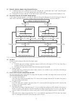
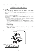
•
Heating output
: Outputs DC12V relay drive signal during heating operation.
•
Compressor ON output
: Outputs DC12V relay drive signal when the compressor is operating.
•
Error output
: When any anomalous condition occurs, it outputs DC12V relay drive signal.
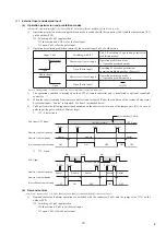
(b) Remote operation input
Remote operation inputs (switch input, timer input) connectors (CnT) are provided on the indoor control PCB.
However, the remote operation by the CnT is not effective when “Center mode” is selected with the air-conditioner.
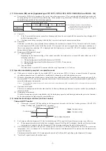
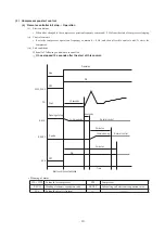
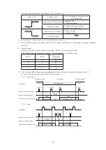
(i) At the shipping from factory [Indoor function of wired remote controller “External input selector” is
set at the level input.]
• Startup at the input signal to CnT OFF
ON [Edge input] … Air-conditioner ON
• Stop at the input signal to CnT ON
OFF [Edge input] … Air-conditioner OFF
*ON
ON
ON
OFF
OFF
OFF
OFF
OFF
OFF
ON
ON
ON
ON
OFF
OFF
*ON
CnT input
Air-conditioner A
Air-conditioner B
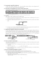
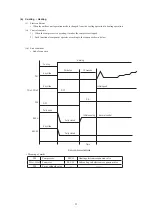
(ii) When the setting is changed to the pulse input at site using the indoor unit function of wired
remote controller “External input selector”
It becomes effective only when the input signal to CnT is changed OFF
➝
ON and the air-conditioner operation [ON/
OFF] is inverted.
ON
ON
OFF
OFF
OFF
OFF
ON
OFF
OFF
ON
ON
CnT input
Air-conditioner A
Air-conditioner B
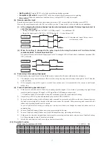
(c) Processing of emergency stop signal
This emergency stop signal is used to stop all indoor unis connected to the same outdoor unit in emergency.
1) The emergency stop control becomes effective if the emergency stop control setting is changed to “Valid” from the
wired controller.
2) If the emergency stop [E-63] signal is received from outdoor unit, it is transmitted to the remote controller and
makes stop.
(d) Fresh air processing operation input
1) If indoor unit controller receive fresh air processing operation signal (*1) or fresh air processing stop signal from
remote controller, it output ON signal or OFF signal from CnD connector respectively.
*1. Operation switch ON at interlock setting and ventilation switch ON at non-interlock setting.
2) Output relay is DC12V option and maximum relay load is LY2F (OMRON).
3) In case of interlock setting, if either of indoor units connected to one remote controller is in the state of anomalous stop,
the fresh air processing unit connected to that indoor unit cannot be operated. Other processing units connected to the
indoor units operating normally can be operate.
In case of non-interlock setting, processing unit can start ventilation even though the connected indoor unit is in
anomalous stop.
4) In case of interlock setting if indoor unit stops, processing unit also stop.
5) In case of interlock setting if indoor unit stops with anomalous stop, processing unit also stop.
6) If indoor unit is started or stopped from center console, processing unit can start or stop in case of interlock setting,
but it keep stopping in case of non-interlock setting.
7) Interlock or non-interlock can be set only on the remote controller.
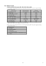
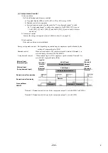
(20) Dip switch function
Model capacity selection with SW6 0 : OFF, 1 : ON
Model
P22
P28
P36
P45
P56
P71
P80
P90
P112
P140
P160
P224
P280
SW6-1
0
1
0
0
0
0
1
0
1
0
1
0
1
SW6-2
0
0
1
0
1
0
0
1
1
0
0
1
1
SW6-3
0
0
0
1
1
0
0
0
0
1
1
1
1
SW6-4
0
0
0
0
0
1
1
1
1
1
1
1
1
Note (1) ON marked with * means ON by a remote
controller switch or other.
Summary of Contents for 112KXE6
Page 105: ... 101 Model FDC335KXE6 A PCB003Z035 shows local wining ...
Page 134: ... 130 PJF012D003 ...
Page 135: ... 131 ...
Page 139: ... 135 PJA012D751 b ...
Page 140: ... 136 ...
Page 206: ... 202 2 model type DIS model type HEAD ...
Page 207: ... 203 2 2 ...
Page 208: ... 204 2 2 2 2 2 ...