


Page 24
MODELS: WS-55859 / WS-55909 / WS-65869 / WS-65909 / WS-73909
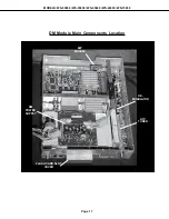
Circuit Adjustment Mode
Most of the adjustments can only be performed using the remote hand unit. Many of the adjustments must be
performed in both the 480i and 1080i modes. Video/Color adjustments must be performed in the 480i and
1080i modes, and data must be preset in the 480P (DVD) and VGA modes.
Note:
Set the Remote Operational Mode to NetCommandTM. (Hold the Power button and press
9-3-5 in sequence.) This slows the remotes response and makes adjustments easier. When
adjustments are complete,
set the Remote to its original Operational Mode.
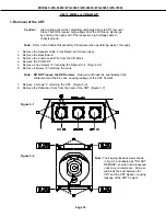
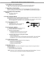
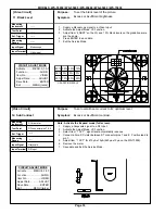
A. Activating the Circuit Adjustment Mode
The current signal source determines if the
activated Adjustment Mode is 480i or 1080i.
1. Select the signal source (480i or 1080i).
2. Press the "MENU" button on a remote hand unit.
3. Press the number buttons "0", "1", "5", "7" in sequence. The
screen will change to the Adjustment Mode.
Note:
Repeat steps 1 and 2 if the circuit
adjustment mode does not appear
on screen.
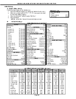
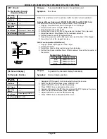
B. Selection of adjustment Functions and
Adjustment Items
To select an adjustment item in the circuit adjustment mode, first select the adjustment function that includes
the specific adjustment item to be selected. Then select the adjustment item. Refer to the following pages for
the listing of adjustment functions and adjustment items.
1. Press the "AUDIO" button on a remote hand unit to select an adjustment function. Each time the button
is pressed, the Function changes in the following sequence:
2. Press the VIDEO button to select a specific Adjustment Item. The Item number increases each time the
VIDEO button is pressed.
C. Changing Data
After selecting an adjustment Item, use the ADJUST UP/DOWN button to change data.
Press ADJUST DOWN to decrease the data value.
Press ADJUST UP to increase the data value.
D. Saving Adjustment Data
Press ENTER to save adjustment data in memory. The character display turns red for approximately one
second in this step.
Note:
If the circuit adjustment mode is terminated without pressing ENTER, changes in adjustment data
are not saved.
VC
JNGL
AUD
SNTS
MNTS
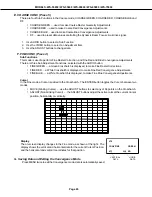
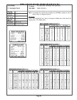
Adjustment Functions
Previous Models
V19 Chassis
Video/Chroma
VC
JungleJNGL
Main Matrix
MNTS
Sub Matrix
SNTS
Audio
AUD
Adjustment Function Name Changes
CHASSIS
V19
MODE
0
ADJ ITEM
1
SCT 42 480i
SIGNAL
ABBREV.
DATA
Summary of Contents for WS-55859
Page 2: ......
Page 61: ...MODELS WS 55859 WS 55909 WS 65869 WS 65909 WS 73909 Page 61 STANDBY SUPPLIES REGULATOR ...
Page 62: ...MODELS WS 55859 WS 55909 WS 65869 WS 65909 WS 73909 Page 62 SWITCHED SUPPLIES REGULATOR ...
Page 63: ...MODELS WS 55859 WS 55909 WS 65869 WS 65909 WS 73909 Page 63 DM POWER SUPPLY ...
Page 64: ...MODELS WS 55859 WS 55909 WS 65869 WS 65909 WS 73909 Page 64 VIDEO COLOR A V SWITCH CIRCUIT ...
Page 65: ...MODELS WS 55859 WS 55909 WS 65869 WS 65909 WS 73909 Page 65 PCB SIGNAL Y C PATH ...
Page 66: ...MODELS WS 55859 WS 55909 WS 65869 WS 65909 WS 73909 Page 66 SYNC PATH ...
Page 67: ...MODELS WS 55859 WS 55909 WS 65869 WS 65909 WS 73909 Page 67 DEFLECTION CIRCUIT X RAY PROTECT ...
Page 68: ...MODELS WS 55859 WS 55909 WS 65869 WS 65909 WS 73909 Page 68 SOUND CIRCUIT ...
Page 69: ...MODELS WS 55859 WS 55909 WS 65869 WS 65909 WS 73909 Page 69 CONVERGENCE CIRCUIT ...
Page 70: ...MODELS WS 55859 WS 55909 WS 65869 WS 65909 WS 73909 Page 70 CONTROL CIRCUIT ...
Page 72: ......
Page 73: ......
Page 74: ......
Page 75: ......
Page 76: ......