Page 23
MODELS: WS-55859 / WS-55909 / WS-65869 / WS-65909 / WS-73909
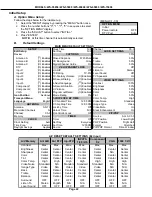
C. A/V Memory
Each of the external inputs has its’ own Audio/Video Memory. A change in an A/V setting at a specific input is
stored in memory for that specific input.
A/V Reset
1. The front panel AV Reset button initializes all A/V Memories.
2. The AV Reset in the user’s menu initializes only the selected input’s A/V Memory.
LED Indicator Diagnostics
The “Power ON LED” provides an indication of the sets operation, and the possible cause of a malfunction.
1. Initial Control Circuitry Check
Immediately after the TV is connected to an AC power source:
2. Error Code Operational Check
Pressing the front panel “DEVICE” and “MENU” buttons at the same time, and holding for 5 seconds,
activates the Error Code Mode. The LED flashes denoting a two digit Error Code, or indicating no problem
has occured since the last Initalization.
Note:
The front panel buttons must used, NOT those on the Remote Control.
•
The number of flashes indicates the value of the MSD (tens digit) of the Error Code.
•
The flashing then pauses for approximately 1/2 second.
•
The LED then flashes indicating the value of the LSD (ones digit) of the Error Code.
•
The Error Code is repeated a total of 5 times.
Example: If the Error Code is “24”, the LED will flash two times, pause, and then flash four
times.
3. Error Codes
The Error Code designations indicating a malfunction, or no malfunction, are listed below:
Remote Control Operational Modes
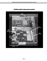
There are two Remote Hand Unit Operational Modes, “Standard” and “NetCommand
TM
”. The Remote is initially
in
in the “Standard” mode. The “NetCommand
TM
” mode is used when controlling Home Theater devices using
NetCommand
TM
. To change the Remote Operational Mode:
• Set the Remote to the TV Layer
•
Point the Remote away from the TV.
•
To change to “Netcommand
TM
” ... Hold the “Power” button and press “9-3-5” in sequence.
•
To change to “Standard” ... Hold the “Power” button and press “0-0-0” in sequence.
LED Indications
Conditions
Probable Cause
Off
After AC is applied Standy Power Supply or TV µPC not running
Fast Blink for 70 sec.
After AC is applied Normal - DM µPC is booting up
Fast Blink (doesn't stop)
After AC is applied TV µPC is running, but DM failed to boot up
Slow Blink
Set is Off
Normal - Timer is set for Automatic Turn ON
Error Code
Probable Cause
12
Normal Operation - No Error Detected
21
X-Ray Protect
22
Short Protect
23
Loss of Horizontal Deflection
24
Loss of Vertical Deflection
Summary of Contents for WS-55859
Page 2: ......
Page 61: ...MODELS WS 55859 WS 55909 WS 65869 WS 65909 WS 73909 Page 61 STANDBY SUPPLIES REGULATOR ...
Page 62: ...MODELS WS 55859 WS 55909 WS 65869 WS 65909 WS 73909 Page 62 SWITCHED SUPPLIES REGULATOR ...
Page 63: ...MODELS WS 55859 WS 55909 WS 65869 WS 65909 WS 73909 Page 63 DM POWER SUPPLY ...
Page 64: ...MODELS WS 55859 WS 55909 WS 65869 WS 65909 WS 73909 Page 64 VIDEO COLOR A V SWITCH CIRCUIT ...
Page 65: ...MODELS WS 55859 WS 55909 WS 65869 WS 65909 WS 73909 Page 65 PCB SIGNAL Y C PATH ...
Page 66: ...MODELS WS 55859 WS 55909 WS 65869 WS 65909 WS 73909 Page 66 SYNC PATH ...
Page 67: ...MODELS WS 55859 WS 55909 WS 65869 WS 65909 WS 73909 Page 67 DEFLECTION CIRCUIT X RAY PROTECT ...
Page 68: ...MODELS WS 55859 WS 55909 WS 65869 WS 65909 WS 73909 Page 68 SOUND CIRCUIT ...
Page 69: ...MODELS WS 55859 WS 55909 WS 65869 WS 65909 WS 73909 Page 69 CONVERGENCE CIRCUIT ...
Page 70: ...MODELS WS 55859 WS 55909 WS 65869 WS 65909 WS 73909 Page 70 CONTROL CIRCUIT ...
Page 72: ......
Page 73: ......
Page 74: ......
Page 75: ......
Page 76: ......


