background image

26

               Chapter . . . 

Connecting: Helpful Hints

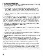
Q  My VCR (or other device) does not have two sets of stereo audio outputs.  How can I connect this  
     device’s audio to both the TV and the A/V Receiver? 

 A.  There are two solutions:

1.  Connect the single set of stereo audio outputs to the TV only.  Use Edit NetCommand® to change the 

setup of this device.  In the Connection screen of “Change” make sure both audio and video for the TV 
input are checkmarked and neither the audio or the video for the AVR input are check marked.  This will 
allow the NetCommand system to use the TV outputs to transfer the device’s audio to the A/V Receiver.  
See 

Edit NetCommand

 in the next chapter for details.

2.  Use RCA type “Y” splitter cables to split the device’s audio output to be connected to both the TV and 

the A/V Receiver.

Q. I have both the TV monitor stereo audio output and TV digital audio output connected to the same       
    input designation on my A/V Receiver.  How do I switch between analog audio and digital audio?

A.  This depends on the individual A/V Receiver.  Some A/V Receivers will switch automatically to digital when 

a digital audio signal is supplied.  Other A/V Receivers can be manually switched by remote control.  For 
these types of A/V Receivers, see 

Edit NetCommand

 in the next chapter for NetCommand control of these 

features.  Some A/V Receivers will require that you make this change on the front panel of the A/V Receiver.

Q. The front panel of my A/V Receiver is too tall or too convex for the IR emitter signal to reach the    
     remote control sensor of the A/V Receiver.  What can I do?

 A.  There are several possible solutions.

1.  Mount the IR Emitter on the top, front edge of the A/V Receiver over the remote control sensor.  Use tape 

to secure it in place.

2.  Mount the IR Emitter on the underside of the shelf above the A/V Receiver (if the A/V Receiver is in a 

cabinet).  Use double sided tape to secure it in place.

3. Some small stick-on emitters from other manufacturers may be compatible with this TV’s IR Emitter jacks.  

These may be used instead of the supplied IR Emitters.

Q. I occasionally need to see the menu from my A/V Receiver.  How can I connect it to the TV for this      
     purpose?

A. You can connect the video output of the A/V Receiver to an unused input on the TV.  Then use Edit 

NetCommand to “Add” this as an “Other” device, not an A/V Receiver.  On the “Connection” screen, indicate 
which TV input was used and checkmark the video box.  Make sure the TV input audio box and both the 
audio and video boxes for the AVR input are not checkmarked.  You should also name this device so you can 
easily identify it on the Device Selection Menu.  You can also use Input 3 (Camcorder) on the front panel.

Q. I have a high definition receiver I would like to connect and it also has an S-video output I would  
     like to be able use as well.  Is there any way to connect this receiver both ways?

A. Yes, this item will appear twice in the Device Selection Menu.  Just add this unit once using the Antenna and 

once using one of the S-video inputs.  Make sure you indicate that this is the same manufacturer for both.  
We suggest that you connect stereo audio outputs with the S-video to the TV so that you do not need to use 
two inputs on the A/V Receiver.  If this is a NetCommand compatible HDTV receiver and HD or SD outputs 
can be switched by remote control, see 

Edit NetCommand

 in the next chapter for NetCommand control of 

this feature.

Summary of Contents for WS-55815

Page 1: ...ord the model and serial numbers of your television This information is on the back of your TV Model number Serial number v i s i t o u r w e b s i t e a t www mitsubishi tv com TM TM Projection Television Owner s Guide WS 55815 WS 65815 ...

Page 2: ...ed by Mitsubishi could cause harmful interference and would void the user s authority to operate this equipment WARNING TO REDUCE THE RISK OF FIRE OR ELECTRIC SHOCK DO NOT EXPOSE THIS APPLIANCE TO RAIN OR MOISTURE CAUTION TO PREVENT ELECTRIC SHOCK MATCH WIDE BLADE OF PLUG TO WIDE SLOT FULLY INSERT NOTE TO CATV SYSTEM INSTALLER THIS REMINDER IS PROVIDED TO CALL THE CATV SYSTEM INSTALLER S ATTENTION...

Page 3: ...es 38 Changing Deleting Devices Finish Screen 42 Device Selection Menu 43 Using the Device Menu Button to Display Menus 44 Chapter 4 IEEE 1394 Devices and NetCommand Controlled Recordings Adding IEEE 1394 Devices Automatically 46 IEEE 1394 Devices Compatibility 48 Using the Guide Button to Display ChannelView and Menus 49 NetCommand Controlled Recordings 50 NetCommand Controlled Peer to Peer Conne...

Page 4: ...and uneven surfaces may cause the appliance and cart combination to overturn 7 Ventilation Slots and openings in the cabinet are provided for ventilation and to ensure reliable operation of the TV and to protect it from overheating Do not block these openings or allow them to be obstructed by placing the TV on a bed sofa rug or other similar surface Nor should it be placed over a radiator or heat ...

Page 5: ... qualified service personnel 17 Damage Requiring Service Unplug the TV from the wall outlet and refer servicing to qualified service personnel under the following conditions a When the power supply cord or plug is damaged b If liquid has been spilled or objects have fallen into the TV c If the TV has been exposed to rain or water d If the TV does not operate normally by following the operating ins...

Page 6: ...ion offers The very core of our corporate philosophy is to provide our customers with the very best Our development team at Mitsubishi has worked to provide you with a television that defines state of the art with the capability to meet your needs now and in the future Whether this is your first Mitsubishi electronic product or an addition to your Mitsubishi collection we believe you and your fami...

Page 7: ...Chapter 1 Television Overview TV Accessories 8 Special Features 8 Front Control Panel Multimedia Access 9 Back Panel 10 Important Notes 12 ...

Page 8: ...signals as 1080i True HDTV Digital Cable Ready CableCARD This HDTV is Plug and Play ready It can descramble a cable provider s one way digital signals with the use of a CableCARD security module The CableCARD is used in place of a traditional cable box to access digital cable programming including high definition Contact your local cable provider for availability information and service details Ne...

Page 9: ...unctions when TV menus are not displayed on the screen The bottom row of labels show the control functions when the TV menus are displayed on the screen or when a special function has been activated See Remote Control Overview page 29 for further details on the functions of these buttons TIMER is also accessible through the menu screens Pressing MENU on the front panel will display the TV menu Mul...

Page 10: ...r NetCommand controlled system Detailed information regarding IEEE 1394 connection requirements are in Chapter 2 2 Antenna ANT 1 MAIN ANT 2 AUX ANT 1 MAIN and ANT 2 AUX can each receive both digital analog over the air channels from a VHF UHF antenna or non scrambled digital analog cable channels Your primary viewing signal source should be connected to ANT 1 MAIN ANT 1 MAIN must be used to view p...

Page 11: ... left and right audio from your DVI device This input is HDCP High Bandwidth Digital Copy Protection compliant 6 DVI Analog Audio Unlike HDMI DVI does not carry audio information on the same cable Use these analog stereo audio inputs when using the HDMI input with a device that outputs DVI instead of HDMI 7 Component Inputs 1 2 YPbPr 480i 480p 1080i These inputs can be used for the connection of d...

Page 12: ... that only partially fill the screen leaving black or colored bars to fill the screen when used over extended periods of time or when viewed repeatedly can cause uneven aging of the phosphors and leave subtle ghosts from the stationary images in the picture Still or stationary images may be received from broadcasters cable channels satellite channels DVD discs video tapes laser discs on line servi...

Page 13: ...let Cable 17 VCR Video and Audio to a Cable Box 18 A V Receiver or Stereo System 19 Satellite Receiver or Other Device with S Video 19 DVD Player with Component Video 20 DVI Device 20 HDMI Device 21 External DTV Receiver with Component Video 21 IR Emitter NetCommand 22 IEEE 1394 Devices 23 IEEE 1394 Device Connection Styles 24 CableCARD Definition and Initial Screen Display 25 Helpful Hints 26 ...

Page 14: ...ecting each device custom name devices add devices not included in the presets above or delete devices no longer used See Helpful Hints at the end of this chapter for additional information on device setup The following charts show which preset inputs you should use on the TV and A V Receiver Chart 1 shows TV inputs Chart 2 shows the A V Receiver inputs used by A V Receiver models already known by...

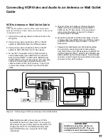
Page 15: ...y Antenna or Cable Primary Wall Outlet Cable 3 CableCARD TM SLOT cover removed Figure 1 Wall Outlet Cable Cable Box compatible with PIP POP Figure 2 3 coaxial cables and one two way RF splitter are required These are not included with the TV It is very important to connect the incoming cable for your primary viewing source to ANT 1 especially for CableCARD use 1 Connect the incoming cable to IN on...

Page 16: ... 3 A 300 Ohm to 75 Ohm transformer is required This is not included with the TV For antennas with twin flat lead 1 For antenna with twin flat leads connect the 300 Ohm twin leads to the 300 Ohm to 75 Ohm transformer 2 Push the 75 Ohm side of the transformer onto ANT 1 MAIN on the TV back panel For antennas with coaxial lead 3 Connect the coaxial lead directly to ANT 1 MAIN on the TV back panel IEE...

Page 17: ...VIDEO VIDEO AUDIO LEFT MONO AUDIO RIGHT INPUT 1 2 ANT 1 MAIN MONITOR OUTPUT AUDIO VIDEO 1 7 3 6 7 HS U748 VCR back panel If your VCR has a video channel or RF ON OFF switch set it to OFF 5 4 5 6 2 S Video recommended if available White Red White Red White Red W h i t e R e d Attach only one cable type IN OUT OUT TWO WAY SPLITTER Incoming Cable 1 2 3 Note NetCommand will assume your VCR is connecte...

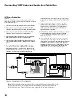
Page 18: ...V CABLE VHF UHF 7 S VIDEO VIDEO AUDIO LEFT MONO AUDIO RIGHT INPUT 1 2 ANT 1 MAIN IN OUT OUT TWO WAY SPLITTER Incoming Cable 1 2 3 MONITOR OUTPUT AUDIO VIDEO 1 9 3 8 Cable Box back panel section IN OUT 2 4 9 HS U748 VCR back panel If your VCR has a video channel or RF ON OFF switch set it to OFF 7 6 7 8 5 4 S Video recommended if available White Red White Red White Red W h i t e R e d Attach only o...

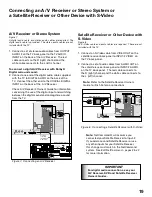
Page 19: ...RATORIES INC ALL RIGHTS RESERVED INPUT 1 OPTICAL INPUT 2 COAXIAL INPUT 3 COAXIAL DIGITAL AUDIO SWITCHED UNSWITCHED AC 120V 60Hz TOTAL 100W 0 9A MAX AC OUTLETS MITSUBISHI AUDIO VIDEO RECEIVER MODEL M VR1000 POWER SUPPLY POWER CONSUMPTION 120V 60Hz 552W 732VA DISTRIBUTED BY MITSUBISHI CONSUMER ELECTRONICS AMERICA INC 6100 ATLANTIC BLVD MADE IN JAPAN NORCROSS GA 30071 1305 FABRIQUE EN JAPAN AVIS RISQ...

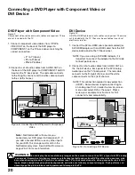
Page 20: ... display the same stationary images on the screen for more than 15 of your total TV viewing in one week Examples of stationary images are letterbox top bottom bars from DVD or other video sources side bars when showing standard TV pictures on widescreen TV s stock market reports video game patterns station logos black or bright closed caption backgrounds web sites or stationary computer images Suc...

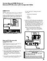
Page 21: ...estrial antenna or cable not satellite to ANT 1 on the TV back panel a coaxial splitter available at most electronic supply stores may be required to complete this installation 3 Connect RCA type cables from the YPrPb outputs on the DTV receiver to either Component 1 or 2 on the TV back panel matching the correct connections DTV Receiver to TV Back panel Y to Y Pr to Pr Pb to Pb 4 Connect the L le...

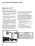
Page 22: ...isplay plastic using a flashlight and is normally a round or square cutout behind the plastic If you cannot see the sensor and the device s Owner s Guide does not specify the If a single emitter end can be placed in a position that will operate more than one device do not use a separate emitter end for the additional device A single device receiving remote control signals from too many emitters or...

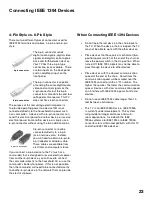
Page 23: ...s a camcorder that is designed to receive electrical power from another 6 pin device you will need to connect the camcorder directly to the household AC or use the camcorder s battery for power If this is not possible then the camcorder will need to be connected directly to another 6 pin device in the network that can provide the electrical power 6 pin to 4 pin adaptor 4 pin connector 6 pin connec...

Page 24: ...om any IEEE 1394 device to other compatible devices Hub Connection Style The IEEE 1394 also offers you the capability to connect your devices using the TV as a hub within the audio video network Each device can send information which may include audio and video to any other device in the network Digital DVD Digital VCR TV Digital DVD 1 Digital VCR 1 D I G I T A L S U R R O U N D S CH Digital DVD 2...

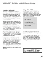
Page 25: ...rogramming by direct connection to a cable system providing such programming A security card CableCARD provided by your cable operator is required to view encrypted digital programming Certain advanced and interactive digital cable services such as video on demand a cable operator s enhanced program guide and data enhanced television services may require the use of a set top box For more informati...

Page 26: ...utions 1 Mount the IR Emitter on the top front edge of the A V Receiver over the remote control sensor Use tape to secure it in place 2 Mount the IR Emitter on the underside of the shelf above the A V Receiver if the A V Receiver is in a cabinet Use double sided tape to secure it in place 3 Some small stick on emitters from other manufacturers may be compatible with this TV s IR Emitter jacks Thes...

Page 27: ...emote Control Functions Overview 30 Operation 31 Care 31 Sleep Timer 31 3D Graphical Menu System 32 NetCommand Initial Setup 33 Edit NetCommand Adding an A V Receiver 35 Adding Devices 38 Changing Deleting Devices Finish Screen 42 Device Selection Menu 43 Using the Device Menu Button to Display Menus 44 3 ...

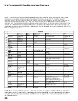
Page 28: ...900 SR HD5 DD 6000 DD 8020 HS U795 HS U778 Bose Lifestyle 28 Lifestyle 28 Denon AVR 2700 Echostar 6000 Funai F260LA General Instruments CFT2200 Hitachi DV P415U VT FX665A Hughes HIRD E45 HIRD E86 Integra DTR 9 1 DPS 9 1 JVC XV S65GD HR VP 650U Kenwood VR2080 Marantz SR8200 Microsoft XBox requires the DVD kit from Microsoft Motorola Several Models Panasonic TU HDS20 DVD A310 PV 8662 Philips VR620CA...

Page 29: ...en Highlight the button and press ENTER to select the function Back Button Use the Back button to navigate back to the previous screen Next Button Use the Next button to navigate forward to the next screen Cancel Button The Cancel button will stop any changes you are currently making without saving them into memory When you select the Cancel button NetCommand will prompt you to confirm that you wa...

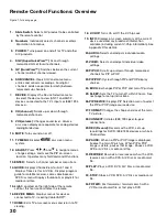
Page 30: ...the right side of the remote control this feature illuminates the remote 16 DEVICE MENU Displays menus for devices connected to TV including CableCARD 17 HOME Exits TV on screen menus and return to TV viewing 18 V CHIP Turns On or Off the V Chip Lock 19 INFO Displays on screen summary of the current device used and any broadcast information available including current V Chip information See Append...

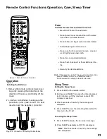
Page 31: ...isplayed by 30 minutes until the maximum value of 120 minutes is reached 3 After 5 seconds of inactivity the message will disappear 4 Press SLEEP to view the remaining time before the timer turns the TV off Canceling the Sleep Timer 1 Press SLEEP to display the on screen message 2 Press SLEEP repeatedly until OFF is displayed Note After 5 seconds of inactivity the message box disappears Care For B...

Page 32: ... highlighted with a yellow outline the text color is yellow On screen instructions shown in the message line at the bottom of the menu provide feature selection and adjustment information Some on screen menu options must be set before other options are available Press ADJUST or to change text boxes Some text boxes have preset labels Other boxes allow you to select letters numbers or characters to ...

Page 33: ...Review or Initial Change and Delete will be grayed out Device Setup Screen Figure 3 If the devices connected to the TV are already in NetCommand memory you can quickly select them at this screen Press ADJUST or to move to each device type Press ADJUST or to select the manufacturer Select Other if the manufacturer is not listed Later you can use the Change setting in the Edit NetCommand option of t...

Page 34: ...orize the available channels for Antenna 1 and Antenna 2 if used You may do that by going to the TV Main menu and selecting Antenna Instructions to memorize channels are found in the Antenna menu section Figure 5 Finish screen Note The Review screen lists the TV input and A V Receiver input used with each device You must correctly identify the inputs you used when you connected the devices If you ...

Page 35: ...this new device After selecting Learn and pressing ENTER the screens that follow are the A V Receiver Inputs screen Figure 7 A V Receiver Input Learn screen Figure 8 A V Receiver Learn screen Figure 9 Name screen Figure 10 Monitor Out screen Figure 11 ending with the Finish screen Figure 12 3 Select Other skip Learn and select Next This will allow the device to appear and will allow Figure 6 A V R...

Page 36: ...eady to learn status 3 Press the button on the A V Receiver s remote control that corresponds to the selected function A check mark will appear and the function name will stop flashing This confirms the signal learned status 4 To test the learned command press ENTER on the TV remote The A V Receiver will perform the selected function The A V Receiver needs to be turned on and the IR emitters prope...

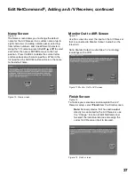
Page 37: ...Change function of Edit NetCommand to select the individual device and assign the correct A V Receiver input to be used Name Screen Figure 10 The Name screen allows you to change the default name for the A V Receiver to a custom name of up to eight characters including a blank space selecting from letters numbers and nine different characters Using the TV s remote press ADJUST or to select each le...

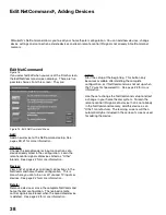
Page 38: ...nd home theater configuration The learned remote control signals are erased when the associated device is deleted See page 42 for more information Mitsubishi s NetCommand allows you to edit your home theater configuration You can add new devices change device settings and connections delete devices and learn remote control IR signals not already in NetCommand memory Figure 13 Edit NetCommand Menu ...

Page 39: ...these options 1 Select a recognized manufacturer The model number optimized for NetCommand will display at the bottom of the screen If a number follows the manufacturer s name example Mitsubishi 1 this indicates additional models are optimized for that manufacturer For many device types non listed models may operate the same way as the listed models do and will use the pre loaded setting After sel...

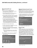
Page 40: ... Screen Figure 16 Shown only if Learn was selected Figure 15 1 Press ADJUST or to select the check box for each function to be learned 2 Press ENTER and the function name will begin to flash to confirm the ready to learn status 3 Press the button on the device s remote control that corresponds to the selected function A check mark will appear and the function name will stop flashing This confirms ...

Page 41: ...e the Standard format for the best quality playback Figure 20 VCR for Recordings screen Edit NetCommand Adding Devices continued RF Connection for Cable Screen Figure 21 The RF Connection screen displays only when adding or changing a cable box If your cable box is connected to a TV Antenna input check the RF checkbox Select the TV antenna input that is used with the cable box Select the channel n...

Page 42: ...ange from the Setup menu screen displays the Change screen To change a device select the device by name not type You can change the name or input connections to the TV and A V Receiver If Other is selected for the manufacturer then you can also Learn The rest of the screens that follow are the same as when you Add a device Figure 23 Change screen Delete Screen Figure 24 Selecting Delete from the S...

Page 43: ...d added to NetCommand Setup an AVR icon will appear in the audio section Press AUDIO to change navigation to the audio section Then press ADJUST or to select the TV speakers icon or the A V Receiver icon Press ENTER to change the audio selection Press DEVICE to return the navigation to the Device Section When you press DEVICE on the TV s remote control the Device Selection menu Figure 26 displays ...

Page 44: ...s ENTER to access the linked page Pressing DEVICE MENU will return to the CableCARD menu screen and pressing HOME will return to TV viewing If there are technical problems with the CableCARD an error screen will automatically display with information that may be needed by your Cable provider when you call them for assistance Press HOME key to exit Using the Device Menu Button to Display Menus Movi...

Page 45: ... Devices Automatically 46 IEEE 1394 Compatibility 48 Using the Guide Button to Display ChannnelView and Menus 49 NetCommand Controlled Recordings 50 Direct VCR Recording 52 NetCommand Controlled Peer to Peer Connections 53 Media Command Media Card Playback 54 Important Notes 56 4 ...

Page 46: ...addition to D VHS This allows you to play analog rental tapes or analog tapes from your established library or make analog recordings from antenna or cable systems To use the analog capability check the Analog Connection box Figure 1 New 1394 Device screen Figure 2 Name for 1394 Device screen Adding IEEE 1394 Devices Automatically When an IEEE 1394 device is connected into the TV network and is po...

Page 47: ...also connected using analog inputs you will need to define the device type Select the type of device such as a VCR Once the device type is selected then the Device screen is displayed so the manufacturer can be selected If the manufacturer is listed then you may be able to control this device while it is operating as an analog VCR For example if the IEEE 1394 device you have added is a Mitsubishi ...

Page 48: ... video and or control information will still be able to pass from one device through the TV to another Compatible IEEE 1394 Devices It is possible to connect devices to the TV that have IEEE 1394 connectors but are not compatible with the TV or with the NetCommand control system Areas of compatibility to consider are device on the network These incompatible devices may not appear on the Device Sel...

Page 49: ...nels in memory If the TV loses power the program listings will be temporarily lost IMPORTANT Devices 1394 or IR Controlled For NetCommand compatible satellite receivers and some cable boxes GUIDE will display the on screen programming guide for the receiver or cable box Press ADJUST or and ENTER to navigate the displayed Guide For NetCommand compatible satellite receivers you may also be able to u...

Page 50: ...remote control to move to the Source Device section 3 Press ADJUST or to select the source device you will record from 4 Press ENTER to confirm selection and return to the Record to section 5 In the Record to section review the destination device VCR and duration Change if necessary 6 Press REC a second time to initiate recording Time Delayed Recording To initiate a time delayed recording 1 Press ...

Page 51: ... List screen A V Disc Search NetCommand is able to search to a specific time in a recording on an IEEE 1394 A V Disc 1 Start the playback of the desired track on the A V disc 2 Use the number buttons to enter the time code position of hours followed by minutes For example to enter one hour and twenty two minutes 1 22 into the track enter 1 2 2 3 Press ENTER to skip to the time code position 4 To c...

Page 52: ...ish a peer to peer connection 1 Press REC on the TV remote 2 Press DEVICE on the remote control to move to the Source Device section 3 Press ADJUST or to select the source device you will record from 4 Press ENTER to confirm selection and return to the Record to section 5 In the Record to section review the destination device example DVCR and duration Change if necessary 6 Press REC a second time ...

Page 53: ...recording You will need to manually stop the recording at the end of the program OR 4 Press the DEVICE MENU button to display the VCR s menu to schedule a delayed recording directly from antenna or cable To record from Ant 1 Ant 2 or other devices see NetCommand Controlled Recordings Restrictions for Traditional VCRs If turned On the TV must be tuned to the Source Device Your VCR must be connected...

Page 54: ...ing Remote Control Buttons for Controlling the Playback For JPEG Pictures Slideshow PLAY begins or resumes slideshow playback PAUSE pauses or resumes playback while in the automatic advance mode FF skips to the next slide REW returns to the previous slide FORMAT single press rotates the slide 90 Multiple press continues to rotate the slide STOP Stop slideshow return to media card screen For MP3 or...

Page 55: ... display Some pictures may be cropped to fit 3 Full path file names can be no longer than 50 characters and must end in a jpg extension Not all 50 characters will display For MP3 or WMA7 Audio files 1 Files recorded with sampling rates of 32 kHz 44 1 kHz or 48 kHz 2 Files recorded with fixed bit rates 3 File names with mp3 or wma extensions NOTE During MP3 or WMA7 audio playback audio from the car...

Page 56: ...r images that only partially fill the screen leaving black or colored bars to fill the screen when used over extended periods of time or when viewed repeatedly can cause uneven aging of the phosphors and leave subtle ghosts from the stationary images in the picture Still or stationary images may be received from broadcasters cable channels satellite channels DVD discs video tapes laser discs on li...

Page 57: ...hapter 5 TV Menu Screen Operations Main Menu Choices 58 Setup Menu 59 NetCommand Menu 61 Antenna Menu 62 Time Menu 64 Captions Menu 65 V Chip Lock Menu 67 Audio Video Menu 70 A V Setting Descriptions 71 ...

Page 58: ...etup If more than one digital recording device is connected use this menu to change the default digital Record To device Turn the transport menu off and change the order of the icons in the Device Selection menu Antenna Figure 3 Memorize available analog and digital channels for Ant 1 and Ant 2 After memorization if a channel displays as digital and analog you can choose to see the channel digital...

Page 59: ...value where 63 is the maximum The default setting for each color is 31 center Highlighted text will show which slider you are adjusting Each active input can be individually adjusted Press ADJUST or to navigate between colors and ADJUST or to change the color slider settings Reset Select to reset the Color Balance settings The settings for the device shown in A V Memory Reset will be returned to t...

Page 60: ...flashing will resume and move the brackets to the next position needing adjustment 5 Press VIDEO to switch between the Red and Blue lines A position is properly converged when all three lines combine to appear white 6 When completed press MENU or HOME to save your changes and exit the Advanced Convergence screen Although there are more than 64 line intersections the flashing bracket only stops at ...

Page 61: ...he icon REW REV FF FWD PLAY STOP Transport Buttons PAUSE REC Detailed information for setting up and editing the NetCommand menu is found in Chapter 3 Edit NetCommand allows you to add new devices change or edit traditional and IEEE 1394 devices turn devices and unused inputs On or Off delete a single device or the entire setup configuration If you choose to delete the entire configuration or if t...

Page 62: ...ng ADJUST or to select the channel 2 By pressing CH or for channels already in memory 3 Directly entering the number With so many current and potential channels the number range is greatly expanded Channels can be one part analog or digital up to the number 16383 or two part for digital channels these use a separator For a two part digital channel you may press SUB CANCEL on the remote to enter a ...

Page 63: ...Viewing and changing SQV banks using the remote control 1 Press the SQV button 2 To change memory banks press a number button within 5 seconds of pressing the SQV button 3 Press the SQV button repeatedly to cycle through the channels available in that bank SQV SuperQuickView Using The Menu Screen Figure 17 SQV SuperQuickView allows you to put together lists of your favorite channels from Antenna 1...

Page 64: ...to On or Off When On you need to select the time and day to turn On and the device and channel to display At your preselected time the timer will turn the TV On and this message will be displayed Press a button for the TV to stay on Press any button on the remote control within 5 minutes or the TV will turn itself Off Set Time Press ADJUST or repeatedly to slowly select the hour or press and hold ...

Page 65: ...s frequently Mitsubishi recommends gray for the background to reduce uneven aging of the picture tubes Note See page 54 for information concerning uneven aging of picture tubes Digital Captions The TV can display one of the following Captions for Digital sources Captions 1 6 Sent by broadcaster On if Mute Closed captions when mute When selected the captioning signal Caption 1 will turn on off by p...

Page 66: ... the same color for the fonts and background Closed Captions will not be visible Captions Menu continued Background Opacity You can customize the background for digital captions using the following categories Transparent See through background to the TV program Translucent TV program is visible behind the background Opaque Solid background blocks TV program Flashing Background flashing in interval...

Page 67: ...fore the V Chip lock takes effect Entry Figures 22 and 23 You will see the screen shown in Figure 22 when you select the V CHIP submenu from the Main menu or after you have canceled your passcode To use the Lock input a four digit passcode with the number buttons on the remote control then press ENTER You can delete a number and move back one space by pressing CANCEL You can exit without inputting...

Page 68: ...S Sexual Situations applies in different degrees to TV PG TV 14 and TV MA V Violence graphic or realistic applies in different degrees to TV PG TV 14 and TV MA When you select a TV rating you are selecting the least restricted program level that can be viewed As an example if you select TV PG you are allowing programs rated TV Y TV Y7 TV G and TV PG to be seen and blocking programs rated TV 14 and...

Page 69: ...he same time will make the Lock by Time active 24 hours a day Front Button Lock Front Button Lock allows you to disable controls on the front panel to prevent anyone from changing settings by accident Select On to lock out the operations of the front panel button and select Off to restore the operations of the front panel buttons If the front panel buttons have been locked and you misplaced the re...

Page 70: ...the device currently being viewed For descriptions of the individual A V settings see A V Setting Descriptions pages 69 and 70 Video Mute Select On to display a blue background when no signal is being received This feature is applicable to all inputs except Ant 1 and Ant 2 Black Enhancement Select On to enhance the contrast in bright scenes for better picture quality Darker scenes will not be affe...

Page 71: ...s SAP will be displayed when you tune to the channel Mono Reduces background noise and should be used when receiving a weak stereo audio signal All audio will be played mono with this setting Listen to is not available for devices connected to the TV inputs component inputs or 1394 devices Level Sound Turn On or Off to automatically equalize the volume level of programs containing significant leve...

Page 72: ...g correction for signals that originated on 24 frames per second film cameras and then were converted for broadcast to 30 frames per second video When the original signals originated on 30 frames per second video cameras the On setting will automatically apply video decoding the same as used with the Off setting Try the On setting when the TV seems to have difficulties and adds too many jagged edg...

Page 73: ...gh Definition Input Connection Compatibility 81 Appendix C Remote Control Programming Codes 82 Appendix D On Screen Information Displays 85 Appendix E NetCommand Specialized Device Keys 86 Appendix F Cleaning and Service 87 Appendix G Diamond Shield Removal 88 Appendix H Cabinet Separation 89 Troubleshooting 90 Additional Information 94 Index 96 Warranty 98 ...

Page 74: ...morphic DVDs with a 2 35 1 aspect ratio Available for analog 480i and 480p and SD 4 3 signals only Stretch Stretches a narrow 4 3 image across the screen with less stretch in the center than the sides Allows the entire narrow image to be displayed across DVD Definitions Anamorphic or Enhanced for Widescreen TV s These DVDs are recorded in a special way to properly show widescreen images on 16 9 TV...

Page 75: ...080i Zoom not available for HD SD 16 9 or analog 1080i not recommended distorted Expand not available for HD SD 16 9 or analog 1080i not recommended distorted Zoom not available for HD SD 16 9 or analog 1080i recommended for anamorphic 2 35 1 Stretch not available for HD SD 16 9 or analog 1080i not recommended distorted Stretch Plus not available for HD SD 16 9 or analog 1080i not recommended dist...

Page 76: ...pictures from other A V components in the POP display Press PAUSE to pause or restart automatic POP switching Selecting POP Live Image Press ADJUST or to select a different POP live image automatic POP switching must be paused Freezing the PIP and Side By Side Picture Press PAUSE to freeze the PIP and side by side images Press PAUSE again to return to a live image MAIN PICTURE Side by Side PIP Ant...

Page 77: ... Device is Viewed or Played Device Remote Control Button A V RECEIVER VCR DVD CABLE DBS CH up down Channel up down Skip Forward Backwards Chapter or Track Channel up down Page up down when guide showing VOL up down Volume Up Down MUTE Mute On Off 0 9 digits number functions number functions number functions QV Last Channel Recall DEVICE Menu 1st press Transport Menu 2nd press Setup Menu display 1s...

Page 78: ...nter or select Enter or select CANCEL Cancel function Cancel function Cancel function or Counter Reset Cancel function GUIDE Digital Channel Guide Track or program list display Digital Channel Guide ADJUST up down left right Skip Forward 30 seconds during playback Skip Backwards 12 seconds during playback Page up down in track list up down left right up down left right PLAY Play Play STOP Stop Sto...

Page 79: ...deletes your old passcode and prompts you to enter a new passcode Press HOME to exit the menu Lock Bypass Instructions Have Been Filed for Future Reference Bypassing Front Button Lock If you have misplaced the remote control you can bypass the front button lock by pressing and holding the MENU button on the front panel for more than 8 seconds IMPORTANT When changing or deleting your passcode you m...

Page 80: ...80 This page intentionally blank ...

Page 81: ...nals This also applies to next generation video game consoles sending 480p or 1080i Component 1 and Component 2 Inputs Input Levels and Timing with Component Video Signals EIA 770 1 and EIA 770 2 Standard Levels Timing Y 1 0Vp p includes sync 75 Ohms Pr 700mVp p 75 Ohms can also receive signals from outputs labeled R Y and Cr Pb 700mVp p 75 Ohms can also receive signals from outputs labeled B Y an...

Page 82: ...devices Note To put the remote in the Legacy Mode configuration repeat Steps 1 and 2 At Step 3 enter the code 000 and release POWER This also returns volume and mute control to the TV from the A V Receiver Cable Brand Code ABC 124 ARCHER 125 CABLEVIEW 105 CITIZEN 122 105 COLOR VOICE 128 129 130 106 107 COMTRONICS 128 129 130 106 107 CURTIS 112 113 DIAMOND 124 125 EAGLE 129 GCBRAND 105 GE 112 113 G...

Page 83: ...026 027 028 020 SHARP 055 056 SIGNATURE 2000 047 055 SONY 048 049 050 073 074 075 SV2000 047 SYLVANIA 051 043 044 047 SYMPHONIC 047 TASHIRO 026 TATUNG 030 031 TEAC 030 047 031 TECHNICS 041 042 043 044 TEKNIKA 044 047 TOSHIBA 021 066 TOTEVISION 026 VECTOR RESEARCH 031 WARDS 055 056 029 064 026 YAMAHA 025 030 031 ZENITH 064 026 DVD Brand Code MITSUBISHI 003 AIWA 261 274 APEX 266 283 BOSE 286 DENON 2...

Page 84: ...ition A V receiver Mitsubishi CD player If you have a Mitsubishi A V receiver the audio position may be used in conjunction with select Mitsubishi CD players Your audio position must be programmed to 010 VCR POWER CHANNEL up down PLAY REC PAUSE STOP FF FWD REW REV Mitsubishi VCRs will be compatible with some additional buttons Cable Boxes and Satellite Receivers POWER CHANNEL up down 0 9 number bu...

Page 85: ...ickView bank 2 9 Day and Time 10 Sleep Timer remaining time 11 PIP source and channel Digital Program 1 Digital Major and Sub channel number 2 Digital Channel Name only if broadcast 3 Signal Type being broadcast received Possible SD 4 3 SD 16 9 or HD 4 Screen format being used Possible SD 4 3 Standard Expand Zoom Stretch Stretch Plus Narrow SD 16 9 or HD Standard Wide Expand 5 Language s being bro...

Page 86: ...ewind Reverse Search REW REV X X X Pause Pause PAUSE X X X Record Record REC X X X Enter digits Enter for channel numbers ENTER X X X Low Speed Out LowSpeed 480i out FORMAT X X X High Speed Out Hi Speed 480p 1080i out FORMAT X X X 1 2 3 4 5 6 7 8 9 0 1 2 3 4 5 6 7 8 9 0 1 2 3 4 5 6 7 8 9 0 X X Input Input Change GUIDE X Sub channel separator Digital Sub channel CANCEL X Chapter Chapter Skip Forwar...

Page 87: ... a soft cloth brush or lint brush If necessary you can vacuum using the brush and hose attachments of your vacuum cleaner Do not use the beater brush section on the grill cloth General Cleaning Warnings DO NOT allow liquid to enter the TV through the ventilation slots or any crevice DO NOT use any strong or abrasive cleaners as these can scratch the surfaces DO NOT use any cleaners with ammonia bl...

Page 88: ...hield towards you and push the top out of the channel then lift straight up to remove it from the bottom channel 3 Wipe off any dust with a lint free cloth and store the shield carefully where it will not be scratched Do not use any cleaners on the anti glare Diamond Shield This completes the Diamond Shield removal 4 Re install the molding clips for a finished look by pushing them back into place ...

Page 89: ... the interlock Tabs are clear from Cabinet Bottom 8 Carefully place lower rear surface of Cabinet Top on floor 9 Once you have moved and positioned the Cabinet Bottom to its desired location reverse the procedure and mount the Cabinet Top on the Cabinet Bottom Be sure to align the Brackets properly KEEP FINGERS CLEAR OF ALL JOINTS Replace the Screws and decorative Plastic Covers that were removed ...

Page 90: ...ommand is setup incorrectly Inputs must match actual connections Review through NetCommand menu The TV s Listen to setting may be set to SAP If using stereo or A V receiver speakers check their input selection If using stereo or A V receiver check that AUDIO 2 of MONITOR OUTPUT on TV s back panel is connected to the A V receiver 9 NetCommand unable to learn specific device keys Device does not use...

Page 91: ...Verify that the function is supported or keys are learned The IR emitter is incorrectly placed Make sure the IR emitter is facing the IR sensor in the device The IR emitter is not plugged into the IR emitter output NetCommand The IR emitter is facing the TV screen causing double signals Be sure that the IR emitter cannot send to the TV 24 The A V Receiver is the selected audio source but there is ...

Page 92: ...us Focus is out of alignment Align Convergence 36 Red or blue color is bleeding or shadowing images Focus is out of alignment Align Convergence 37 There is no audio and video from the IEEE 1394 device The device is not turned on turn the device power on No media tape or disc is inserted into the device The media is blank has no recording The play command failed Try pressing play again on the devic...

Page 93: ... not support copyrighted material Source for recording is copyrighted Too many IEEE 1394 devices in network Insufficient bandwith available Disconnect unused devices Source Device has higher speed S 400 than record device If possible reverse devices play in the slower device and record in the faster device 45 Cannot control the IEEE 1394 device from the Transport Menu Device may not support the co...

Page 94: ...tings are retained WARNING This product contains chemicals known to the State of California to cause cancer and or birth defects or other reproductive harm Additional Information From time to time Mitsubishi may offer software updates to expand the features or operation of this TV When these updates are available they will be announced on our web site Mitsubishi tv com If you return your Owner s r...

Page 95: ...aboratories Inc HDMI the HDMI logo and High Definition Multimedia Interface are trademarks or registered trademarks of HDMI Licensing LLC Manufactured under license from Dolby Laboratories Dolby and the double D symbol are registered trademarks of Dolby Laboratories Lifestyle 28 is a trademark of the Bose Corporation XBox is a trademark of the Microsoft Corporation Playstation 2 is a trademark of ...

Page 96: ...ponent Video 20 DVI Device 20 External Devices NetCommand Setup 14 HDMI Device 21 IEEE 1394 Devices 23 IR Emitter NetCommand 22 Satellite Receiver with S Video 19 Single Analog Antenna 16 Separate UHF and VHF Antennas 16 Wall Outlet Cable 15 VCR Video and Audio to an Antenna 17 a Cable Box 18 a Wall Outlet Cable 17 Connection Helpful Hints 26 Device Screen 41 Convergence 59 60 Copy Protected Mater...

Page 97: ...PIP Device Selection Menu 43 Power On Off Devices 43 Prefer Digital 62 Programming the Remote to Control NetCommand A V Products 82 Other Brands of Audio and Video Products 82 R Record List Screen 51 Record To Screen 50 Recordings 50 51 52 Remote Control Buttons 32 Functions 30 31 Care 31 Operation 31 Overview 30 Sleep Timer 31 Traditional VCRs 52 Transport Buttons 61 Reset Factory Defaults Menu 6...

Page 98: ...evision is located within the geographic territory customarily covered by an authorized MITSUBISHI service center If not you must either deliver your television to an authorized service location at your own expense or pay for any travel and or transportation costs the service center may charge to and from your home Actual service labor will be provided without charge c Proof of purchase date from ...

Page 99: ...ht or other intellectual property laws and treaties This License Agreement grants you no rights to use such content except that you own the media on which the Software is recorded but MDEA and its licensors retain ownership of the Software itself All rights not expressly granted are reserved by MDEA 5 EXPORT RESTRICTIONS MDEA is licensing the Software for use within the United States You agree tha...

Page 100: ...e U S A 871D406A10 If you have questions regarding your television call Consumer Relations at 800 332 2119 or email us at MDEA Service mdea com To order replacement or additional remote controls or Owner s Guides call 800 553 7278 or visit our website at www mitsubishi tv com ...

Reviews: