


7-4
Convergence Output Circuitry
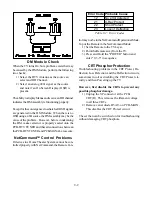
Figure 7-4
shows the Convergence Output circuitry
located on the PCB-Power. The correction signals
Figure 7-4: Convergence Output Circuitry
are amplified and directed to the Sub Vertical and
Sub Horizontal coils located within their respective
red, green and blue Deflection Yokes.
Summary of Contents for WS-48513
Page 2: ......
Page 4: ......
Page 17: ...11 Figure 13 V23 Chassis DVI Input Block Diagram ...
Page 22: ...1 4 Figure 1 4 PCB Locations Figure 1 5 Main Component Locations ...
Page 40: ...3 10 ...
Page 70: ...8 2 Figure 8 2 Overall Sound Circuitry Block Diagram ...
Page 72: ...8 4 ...
Page 75: ......


