


3-6
When PON-1 goes High, Q9A21 turns Off, allowing
Q9A20 to turn On. With Q9A20 conducting, the 12V
supply is generated from the 12VS supply. The 12V
supply enables IC9A22 and the 5V-1 supply is gener-
ated.
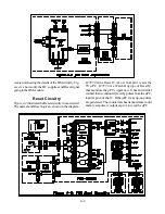
Time Shift Supply Power Distribution
Figure 3-8
illustrates the Power Distribution for the Time
Shift supplies. The 5V-1 supply is used by the MLink,
3DYC and Signal Select circuitry. It is also the source
for the 3.3V-2 supply, which is directed to the Conver-
Summary of Contents for WS-48513
Page 2: ......
Page 4: ......
Page 17: ...11 Figure 13 V23 Chassis DVI Input Block Diagram ...
Page 22: ...1 4 Figure 1 4 PCB Locations Figure 1 5 Main Component Locations ...
Page 40: ...3 10 ...
Page 70: ...8 2 Figure 8 2 Overall Sound Circuitry Block Diagram ...
Page 72: ...8 4 ...
Page 75: ......


