background image

EN-17

ENGLISH

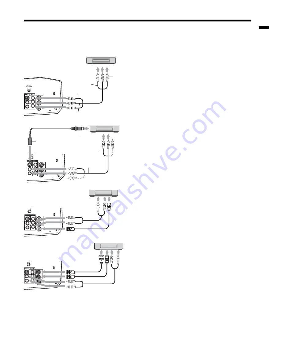
Connecting to a video player, etc.

1.  Connect one end (yellow) of the supplied audio/video cable 

to the VIDEO IN terminal of the projector. 

2.  Connect one end (white and red) of the supplied audio/

video cable to the audio input terminals (L/MONO, R) of the 
projector. 

3.  Connect the other end (yellow) of the audio/video cable to 

the video output terminal of the video equipment. 

4.  Connect the other end (white and red) of the audio/video 

cable to the audio output terminals (L, R) of the video 
equipment. 

When the video equipment is equipped with the S-video 
output terminal, make the connection as follows: 

1.  Connect one end of a commercially available S-video cable 

to the S-VIDEO IN terminal of the projector. 

2.  Connect the other end of the S-video cable to the S-video 

output terminal of the video equipment. 

3.  Connect one end (white and red) of the supplied audio/

video cable to the audio input terminals (L/MONO, R) of the 
projector. 

4.  Connect the other end (white and red) of the audio/video 

cable to the audio output terminals (L, R) of the video 
equipment. 

When using the BNC connector:

(For VIDEO input)
•  When the video output terminal of the connected video 

equipment is BNC type, use the VIDEO IN terminal (BNC 
type). 

•  Select VIDEO as the input source. 
•  When using the VIDEO IN terminal (BNC type) and the 

VIDEO IN terminal (RCA type) at the same time, the video 
signal input to the VIDEO IN terminal (RCA type) takes 
priority. 

When using the BNC connector:

(For S-VIDEO input)
•  When the video output terminals of the connected video 

equipment are BNC (Y/C) type, connect Y and C to the 
S-VIDEO IN (Y and C) terminals (BNC type) respectively.  

•  Select S-VIDEO as the input source. 
•  When using the S-VIDEO IN (Y and C) terminals (BNC type) 

and the S-VIDEO IN terminal (S type) at the same time, the 
video signal input to the S-VIDEO IN terminal (S type) takes 
priority. 

•  When connecting a monophonic video device, use the white (L) terminal to connect the audio cable. (The same 

audio signal is output from the channels L and R of the AUDIO OUT terminal.) 

•  Also read the instruction manual of the equipment to be connected. 
•  Contact your dealer for details of connection.

When a TV tuner or VCR is connected:

When you use this projector with a TV tuner or VCR connected, no image may appear or a message of “NO SIGNAL” 
may appear on the screen when you change the channel via any channel that is not being received. In such a case, 
set the channels of the TV tuner or VCR again. To avoid such symptom, use the TV tuner or VCR with its channel skip 
function (that is a function not to display channels that are not being received) enabled. 

Viewing video images

A. Connecting the projector to video equipment

Preparation:

•  Make sure that the power of the projector and that of the video equipment are turned off.

1

2

3

4

1

3

4

2

To VIDEO 
IN terminal

To video 
output 
terminal

Video player, or the like

To S-VIDEO 
IN terminal

S-video cable (option)

To S-video 
output 
terminal

Video player, or the like

Audio/video 
cable

To audio input 
terminals

To audio 
output 
terminals

To audio 
input 
terminals

Audio/video 
cable

To audio 
output 
terminals

To VIDEO IN 
terminal (BNC)

BNC cable 
(option)

To video 
output 
terminal

Video player, or the like

To S-VIDEO IN 
(Y and C) terminals 
(BNC)

BNC cable (option)

To S-video (Y/C) 
output terminals

Video player, or the like

Summary of Contents for WD2000U

Page 1: ...WD2000 DLP PROJECTOR MODEL WD2000 User Manual This User Manual is important to you Please read it before using your projector ENGLISH ...

Page 2: ... specified power supply cord If you use another power supply cord it may cause interference with radio and television reception Use the attached RGB cable and RS 232C cable with this equipment so as to keep interference within the limit of a FCC Class B device This apparatus must be grounded DO NOT LOOK DIRECTLY INTO THE LENS WHEN THE PROJECTOR IS IN THE POWER ON MODE CAUTION Not for use in a compu...

Page 3: ... for used electrical and electronic product Please help us to conserve the environment we live in Trademark Registered trademark DLP Digital Micromirror Device DMD and BrilliantColorTM are trademarks or registered trademarks of Texas Instruments Microsoft or Windows are either registered trademarks or trademarks of Microsoft Corporation in the United States and or other countries The trademark of ...

Page 4: ...ids Never push objects of any kind through openings of this projector as they may touch dangerous voltage points or short out parts that could result in a fire or electric shock Never spill liquid of any kind on the projector 14 Servicing Do not attempt to service this projector by yourself Refer all servicing to qualified service personnel 15 Damage requiring service Unplug this projector from the ...

Page 5: ...en 41 F 5 C and 104 F 40 C Operating humidity between 30 and 90 Never put any heat producing device under the projector so that the projector does not overheat Do not attach the projector to a place that is unstable or subjected to vibration Do not install the projector near any equipment that produces a strong magnetic field Also refrain from installing near the projector any cable carrying a larg...

Page 6: ...ould be used Dispose of used batteries according to your local regulations Batteries may explode if misused Do not recharge disassemble or dispose of them in fire Be sure to handle the batteries according to the instructions Load the batteries with its positive and negative sides correctly oriented as indicated on the remote control Keep batteries out of reach of children and pets Remove the batter...

Page 7: ...OMPUTER COMPONENT VIDEO IN 1 terminal Mini D SUB 15 pin 5 AUDIO IN 1 terminal Mini jack 6 Power terminal for wireless LAN unit DC OUT 5V 1 5A MAX Do not use the power terminal as a power for other devices than the specified wireless LAN unit Wireless LAN unit isn t packaged together with the projector Important While the menu or the screen for the keystone lens shift and zoom focus adjustment or pa...

Page 8: ...Even when you keep holding down the LASER button it is emitted only one minute To keep emitting it longer press the LASER button again You can disable the LASER button to prevent laser radiation due to misuse of the button How to disable the LASER button While holding the LASER button down press the button 3 times How to enable the LASER button While holding the LASER button down press the button ...

Page 9: ...o sensor front or rear of the projector When operating the remote control keep the distance from the remote control to the projector via the screen within about 7 m The operable range of the remote control however depends on the characteristics of the screen Using the wired remote control Attached remote control for this projector can be used as a wired remote control with remote control cable Wir...

Page 10: ...ector 3 Put the adjustment feet back into the projector by rotating the adjustment feet You can adjust the vertical and horizontal position of the displayed image using the LENS SHIFT but ton See page 11 Keystone adjustment To correct vertical and horizontal keystone distor tion press the KEYSTONE button on the projector or the remote control to display KEYSTONE and adjust the image by pressing th...

Page 11: ... Every time the button is pressed the image moves to the left When you hold down these buttons for 2 seconds or longer the displayed image moves fast in the corresponding directions Be careful not to be caught in the opening in the lens while the lens is moving Front projection ceiling mounting For ceiling mounting you need the ceiling mount kit designed for this projector Ask a specialist for ins...

Page 12: ...0 5 9 314 8 0 49 125 9 23 13 33 200 508 98 249 174 443 17 2 44 308 7 8 420 10 7 65 166 12 31 17 44 250 635 123 311 218 553 21 5 55 386 9 8 525 13 3 82 208 15 39 22 55 275 699 135 342 240 609 23 7 60 425 10 8 578 14 7 90 228 17 43 24 61 Screen size and projection distance Refer to the following table to determine the screen size When the aspect ratio of the screen is 16 9 When the aspect ratio of t...

Page 13: ... to the DVI terminal of the computer When viewing images supplied from a digital connected computer press the DVI D HDCP button on the remote control Turn on the main power switch of the projector before starting the computer For audio connection 1 Connect one end of a commercially available PC audio cable to the AUDIO IN 1 2 terminal of the projector 2 Connect the other end of the PC audio cable ...

Page 14: ... your hand wet It may cause electric shock Earthing terminal Power cord Example Viewing computer images continued About DDC The COMPUTER COMPONENT VIDEO IN 1 terminal of this projector complies with the DDC1 2B standard and the COMPUTER COMPONENT VIDEO DVI D HDCP terminal complies with the DDC2B standard When a computer supporting this standard is connected to this terminal the computer will autom...

Page 15: ... switched from COMPUTER 1 to COMPUTER 2 to DVI at every press of the COMPUTER button on the projector The projector automatically selects the appropriate signal format The selected signal format is displayed on the screen The COMPUTER COMPUTER 1 COMPUTER 2 and DVI D HDCP buttons don t function while the menu is being displayed Though it may take some time before an image is displayed on the screen...

Page 16: ...r back on Before shutting down the projector be sure to close the menu screen If you shut down the projector without closing the menu the setting data of the menu may not be saved If you shut down the projector while controlling the projector using the network function the application software such as ProjectorView may fail For details see the User Manual for LAN Control Utility contained in the C...

Page 17: ...pe connect Y and C to the S VIDEO IN Y and C terminals BNC type respectively Select S VIDEO as the input source When using the S VIDEO IN Y and C terminals BNC type and the S VIDEO IN terminal S type at the same time the video signal input to the S VIDEO IN terminal S type takes priority When connecting a monophonic video device use the white L terminal to connect the audio cable The same audio si...

Page 18: ... the type of the digital data transfer method they use Some DVD players are provided with a function to switch the methods to output DVI Digital signals When your DVD player is provided with such function set it as follows EXPAND or ENHANCED NORMAL See the users guide of your DVD player for details When your digital device does not have such function adjust the BRIGHTNESS to 16 and CONTRAST to 17 ...

Page 19: ...ess of the VIDEO button on the projector The VIDEO and S VIDEO buttons don t function while the menu is being displayed Though it may take some time before an image is displayed on the screen depending on the type of the input signal such symptom is not a malfunction Some images become easier to view when the setting of aspect ratio is changed See page 21 When projecting images from a DVD player t...

Page 20: ... after shutting it down because the lamp s life may be shortened Wait about 10 minutes before turning the projector back on Before shutting down the projector be sure to close the menu screen If you shut down the projector without closing the menu the setting data of the menu may not be saved If you shut down the projector while controlling the projector using the network function the application ...

Page 21: ...r button 3 Select your desired aspect ratio by pressing the or button When 16 9 is selected 4 Press the ENTER button 5 Select your desired position by pressing the or button To cancel the menu 6 Press the MENU button Important When a 16 9 image is kept displayed for a long time before displaying 4 3 image the afterimages of the black bars may appear on the 4 3 image screen Consult your dealer in t...

Page 22: ...INVERT AUTO POWER ON ON OFF RESET ALL OK AUTO POWER OFF ON OFF FEATURE MENU POSITION 1 Upper left 2 Lower right IMAGE REVERSE SPLASH SCREEN BLUE BLACK BACK COLOR STANDARD LOW LAMP MODE AUTO 16 9 FULL ASPECT DISPLAY INPUT PASSWORD FUNCTION ON OFF SCART INPUT VIDEO SIGNAL AUTO NTSC PAL SECAM 4 43NTSC PAL M PAL N PAL 60 LANGUAGE English Español Deutsch Français Italiano SIGNAL HORIZ POSITION HOLD SET...

Page 23: ...projected image See page 25 2 INSTALLATION menu ITEM SETTING FUNCTION LAMP MODE STANDARD Select this option when you want to view images in a well lit room LOW Select to moderate the intensity of the lamp The operating sound is reduced and the lamp lifetime becomes longer When the lamp mode is switched the projected image may flicker This is not a product malfunction Frequent switching of the lamp ...

Page 24: ...tle while to display images of WXGA and XGA60 signals Even if WXGA is set to AUTO some images of WXGA signal may not be displayed correctly See page 36 for details When WXGA is set to other than AUTO and OFF TRACKING isn t adjusted automatically When wide strips ap pear adjust TRACKING in the SIGNAL menu See page 27 When SCART INPUT is set to ON nothing is output to the external monitor When SCART...

Page 25: ...e 22 for menu setting 1 Display the IMAGE menu 2 Select COLOR or TINT by pressing the or button COLOR or TINT is not available with certain signals TINT is available only when the NTSC signal is input 3 Adjust the selected item by pressing the or button To cancel the menu 4 Press the MENU button COLOR Use to adjust the color thickness of the projected image Every time the button is pressed the col...

Page 26: ...AGE menu CONTRAST B 0 BRIGHTNESS R 0 CONTRAST R COLOR TEMP USER 0 CONTRAST G 0 BRIGHTNESS G 0 BRIGHTNESS B 0 Color Enhancer You can set the user defined balance between the brightness and hue using the menu See page 22 for menu setting With the IMAGE menu 1 Display the IMAGE menu 2 Select COLOR ENHANCER by pressing the or button 3 Select USER by pressing the or button 4 Press the ENTER button 5 Sel...

Page 27: ...ERT SYNC in the SIGNAL USER menu Select AUTO for normal use Noise appears on the right or left half of the image Adjust SHUTTER LS or SHUTTER RS in the SIGNAL USER menu Noise appears on the top or bottom part of the image Adjust SHUTTER U or SHUTTER L in the SIGNAL USER menu 1 Display the SIGNAL menu 2 Press the or button to select an item to adjust 3 Adjust the selected item by pressing the or bu...

Page 28: ...utton The screen for setting the password function will appear 5 Press the ENTER button The screen for entering a password will appear 6 Press the or button to select a number from 0 to 9 7 Press the button You can set the next digit 8 Repeat steps 6 and 7 to set a 4 digit password 9 Enter the password again for confirmation using the same steps 10 Select OK and press the ENTER button If the entere...

Page 29: ... power is turned on Mouse pointer Use to move the cursor on the image instead of the computer mouse R CLICK button This operates in the same way as the right button on the com puter mouse Left click button This operates in the same way as the left button on the com puter mouse HOME button Press to jump back to the first page END button Press to jump to the last page Page Up button Press to go back ...

Page 30: ... the PJLink application software is required For the specifications of PJLink access to the Web site of Japan Business Machine and Information System Industries Association JBMIA This projector is fully compliant to the specifications of JBMIA PJLink Class 1 It supports all the commands defined by PJLink Class 1 and the compliance has been verified with the PJLink standard specifications Version 1 0 Co...

Page 31: ...lation grilles Relocate the projector to a cooler place Wait until the STATUS indicator goes out then press the POWER button If the above solution is not effective replace the lamp Replace the lamp Change with a new lamp if this problem recurs Close the cover correctly Contact your dealer 1 Duration when LAMP MODE of the INSTALLATION menu is set to LOW When it is set to STANDARD this duration will...

Page 32: ...t 4750 hours 1 the replacement message LAMP EXCHANGE will appear on the screen for 1 minute every 25 hours 1 thereafter When the lamp operation time exceeds 5000 hours 1 2 the projector automatically shuts off and can t be used until the lamp is replaced and the lamp operation time is reset 1 Duration when LAMP MODE of the INSTALLATION menu is set to LOW When it is set to STANDARD this duration wi...

Page 33: ...ver isn t attached securely Be sure to reset the lamp operation time whenever you replace the lamp Do not reset the lamp operation time unless you replace the lamp The lamp is fragile If it is broken be careful not to cut yourself with glass fragments Contact your dealer for a new lamp This projector uses a lamp that contains mercury Disposal of the lamp or the projector with the lamp may be regul...

Page 34: ...htning Cancel the AV mute by pressing the MUTE button Check that the lens cap is removed It may take about 1 minute for the lamp to light up The lamp fails to light up on rare occasions In such a case wait for a few minutes and then try again If the projector was turned off before the lamp was cooled down sufficiently last time the fan may start rotating and the POWER button may not work after the ...

Page 35: ...rizontal streak noise may appear on the projected image depending on the type of the DVD player or game console you use In such a case you can reduce such streak noise by enabling the LPF Connect the plugs of the cables to external devices securely Keep the projector away from devices that emit interfering radio waves When the keystone adjustment is carried out the image may not be displayed corre...

Page 36: ...ure stays high the lamp goes out Eliminate any causes of the rise in the ambient temperature This indication appears when the air inlet or outlet grille is blocked When they are kept blocked the lamp goes out Remove the objects blocking the air inlet or outlet grille This mark appears when ineffective operation is carried out This isn t a product malfunction Check that the batteries are loaded in ...

Page 37: ...43 PAL M PAL N PAL 60 480i 480p 576i 576p 720p 1080i Panel resolution 1280 x 768 dots Signal type Terminal type Line Analog RGB Mini D SUB 15 pin 1 Analog RGB 5 BNC 1 Digital RGB DVI 1 Signal type Terminal type Line Video input RCA BNC 1 S video input S 2 BNC 1 Signal type Terminal type Line RGB Component Stereo mini jack ø3 5 2 Video RCA L R 1 S video RCA L R 1 Signal type Terminal type Line Anal...

Page 38: ...74 92 1024 x 768 1024 x 768 HP72 1280 x 1024 78 13 72 00 960 x 768 960 x 768 SUN66a 1152 x 900 61 85 66 00 980 x 768 980 x 768 SUN76a 1152 x 900 71 81 76 64 980 x 768 980 x 768 SUN66 1280 x 1024 71 68 66 68 960 x 768 960 x 768 SUN76 1280 x 1024 81 13 76 11 960 x 768 960 x 768 SGI72 1280 x 1024 76 92 72 30 960 x 768 960 x 768 SGI76 1280 x 1024 82 01 76 00 960 x 768 960 x 768 Specifications continue...

Page 39: ...UB 15 pin Pin No Spec DVI D HDCP DVI D 24 pin PIN No SPEC PIN No SPEC 1 DATA 2 13 2 DATA 2 14 5V Power 3 DATA 2 Shield 15 Ground 4 16 Hot Plug Detect 5 17 DATA 0 6 DDC Clock 18 DATA 0 7 DDC Data 19 DATA 0 Shield 8 20 9 DATA 1 21 10 DATA 1 22 Clock Shield 11 DATA 1 Shield 23 Clock 12 24 Clock 17 24 16 9 8 1 Connectors Dimension Drawings unit mm 1 5 6 9 Factory defaults Without terminal cover Factor...

Page 40: ...nfo meuk mee com Asia CHINA Mitsubishi Electric Air Conditioning Visual Information Systems Shanghai Ltd 26 F Oriental Center 699 Nanjing Rd W Shanghai 200041 China Sales Inquiries Phone 86 21 5211 0882 3010 Fax 86 21 5211 0576 Technical Inquiries Phone 86 21 5211 0882 3018 Fax 86 21 5211 0576 HONG KONG Mitsubishi Electric Ryoden Air Conditioning Visual Information Systems HongKong Ltd 7th Floor M...

Reviews: