background image

5

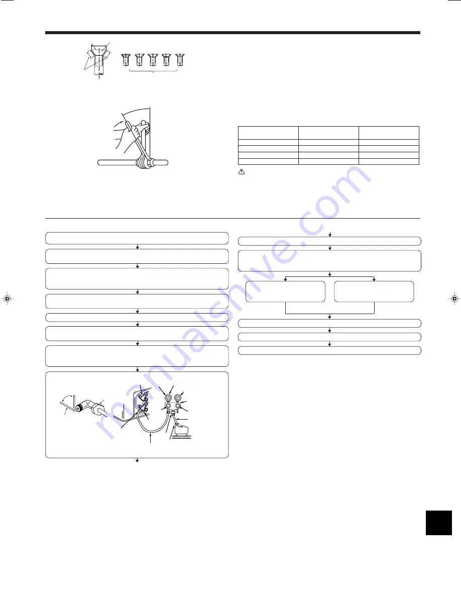
• Apply a thin coat of refrigeration oil on the seat surface of pipe. (Fig. 5-8)
• For connection first align the center, then tighten the first 3 to 4 turns of flare nut.
• Use tightening torque table below as a guideline for indoor unit side union joint section,

and tighten using two wrenches. Excessive tightening damages the flare section.

Copper pipe O.D.

Flare nut O.D.

Tightening torque

(mm)

(mm)

 (N·m)

ø6.35

17

14 - 18

ø9.52

22

34 - 42

ø12.7

26

49 - 61

ø15.88

29

68 - 82

 Warning:

Be careful of flying flare nut! (Internally pressurized)
Remove the flare nut as follows:
1. Loosen the nut until you hear a hissing noise.
2. Do not remove the nut until the gas has been completely released (i.e., hiss-

ing noise stops).

3. Check that the gas has been completely released, and then remove the nut.

Fig. 5-8

5.5. Purging procedures leak test

c

b

a

d

e

f

g

h

i

Fig. 5-7

*Close

*Open

Hexagonal wrench

Stop valve

*4 to 5 turns

Stop valve

(or the vacuum
pump with the
function to
prevent the back
flow)

Gauge manifold
valve (for R410A)

Pressure gauge
    (for R410A)

Compound pressure
gauge (for R410A)

-0.101 MPa
(-760 mmHg)

Handle
Low

Handle High

Window

Charge hose
(for R410A)

Vacuum
pump

Adapter for
preventing
the back flow

Charge hose
(for R410A)

Service port

Stop
valve

5. Refrigerant piping work

PURGING PROCEDURES

Connect the refrigerant pipes (both the liquid and gas pipes) between the indoor
and the outdoor units.

Remove the service port cap of the stop valve on the side of the outdoor unit gas pipe.
(The stop valve will not work in its initial state fresh out of the factory (totally closed
with cap on).)

Connect the gage manifold valve and the vacuum pump to the service port of the
stop valve on the gas pipe side of the outdoor unit.

Run the vacuum pump. (Vacuumize for more than 15 minutes.)

Check the vacuum with the gage manifold valve, then close the gage manifold valve,
and stop the vacuum pump.

Leave it as is for one or two minutes. Make sure the pointer of the gage manifold
valve remains in the same position. Confirm that the pressure gage show -0.101
MPa (-760 mmHg)

5.2.5. Check (Fig. 5-7)

• Compare the flared work with a figure in right side hand.
• If flare is noted to be defective, cut off the flared section and do flaring work again.

a

Smooth all around

b

Inside is shining without any scratches

c

Even length all around

d

Too much

e

Tilted

f

Scratch on flared plane

g

Cracked

h

Uneven

i

Bad examples

Pipe length :

7 m maximum

No gas charge is needed.

Pipe length exceeding 7 m

Charge the prescribed

amount of gas.

Remove the gage manifold valve quickly from the service port of the stop valve.

After refrigerant pipes are connected and evacuated, fully open all stop valves on
gas and liquid pipe sides.
Operating without fully opening lowers the performance and causes trouble.

Tighten the cap to the service port to obtain the initial status.

Retighten the cap

Leak test

B

Summary of Contents for SUZ-KA71VA2

Page 1: ...ners SUZ KA25 KA35 KA50 KA60 KA71VA English INSTALLATION MANUAL For safe and correct use read this manual and the indoor unit installation manual thoroughly before installing the air conditioner unit FOR INSTALLER ...

Page 2: ...ld result in a fire or an electric shock Attach the electrical part cover to the indoor unit and the service panel to the outdoor unit securely If the electrical part cover in the indoor unit and or the service panel in the outdoor unit are not attached securely it could result in a fire or an electric shock due to dust water etc Be sure to use the part provided or specified parts for the installa...

Page 3: ... right or rear side SUZ KA50 KA60 KA71VA A 100 mm or more B 350 mm or more C 500 mm or more When the piping is to be attached to a wall containing metals tin plated or metal netting use a chemically treated wooden piece 20 mm or thicker between the wall and the piping or wrap 7 to 8 turns of insulation vinyl tape around the piping Units should be installed by licensed contractor accordingly to loc...

Page 4: ... 12 m max of 10 SUZ KA50 KA60 KA71 max 30 m max 30 m 15 m max of 10 MFZ Height difference limitations are binding regardless of which unit indoor or outdoor is positioned higher Refrigerant adjustment If pipe length exceeds 7 m additional refrigerant R410A charge is required The outdoor unit is charged with refrigerant for pipe length up to 7 m Up to 7 m No additional charge is required Pipe lengt...

Page 5: ...d gas pipes between the indoor and the outdoor units Remove the service port cap of the stop valve on the side of the outdoor unit gas pipe The stop valve will not work in its initial state fresh out of the factory totally closed with cap on Connect the gage manifold valve and the vacuum pump to the service port of the stop valve on the gas pipe side of the outdoor unit Run the vacuum pump Vacuumi...

Page 6: ...ed main switch fuse D Grounding For Power supply Connect cable from the indoor unit correctly on the terminal block Use the same terminal block and polarity as is used with the indoor unit For aftercare maintenance give extra length to connecting cable Both end of connecting cable extension wire are peeled off When too long or connected by cutting off the middle peel off power supply cable to the ...

Page 7: ...1 S2 S3 S1 S2 S3 Warning There is high voltage potential on the S3 terminal caused by electrical circuit design that has no electrical insulation between power line and communication signal line Therefore please turn off the main power supply when servicing And do not touch the S1 S2 S3 terminals when the power is energized If isolator should be used between indoor unit and outdoor unit please use...

Page 8: ...e be sure to put the contact address telephone number on this manual before handing it to the customer HEAD OFFICE TOKYO BLDG 2 7 3 MARUNOUCHI CHIYODA KU TOKYO 100 8310 JAPAN BG79U686K01 Printed in Thailand ...

Reviews: