


28
5 WIRING
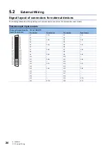
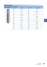
5.2 External Wiring
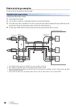
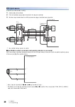
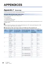
RTD input module
Follow the procedure below for wiring.
1.
Install a relay terminal block.
2.
Connect resistance temperature detectors to the relay terminal block.
3.
Wire the relay terminal block to a RTD input module using an external device connector.
*1 Use a shielded cable and ground the shields.
■
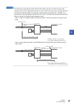
Specifications when a resistance temperature detector is connected
When connecting a resistance temperature detector to the RTD input module, make sure that the conductor resistance values
of three wires satisfy the conditions below.
• Each conductor resistance of
,
, and
must be 350
or lower.
• The difference of conductor resistance values between
and
must be 10
or lower when Pt100, JPt100, or Ni100 is
used, 5
or lower when Pt50 is used.
CH1
A
B
b
CH8
A
B
b
CH1
A
B
b
CH8
A
B
b
A1
A2
B1
A19
B18
B19
Cable
*1
Cable
*1
Relay
terminal block
Cable
*1
External device
connector
RTD input module
A/D
conversion
circuit
A/D
conversion
circuit
A1
B1
b1
RTD
Ò
Ô
Ó
RTD input module
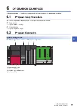
Summary of Contents for R60RD8-G
Page 2: ......
Page 14: ...12 MEMO ...
Page 18: ...16 1 PART NAMES MEMO ...
Page 24: ...22 4 PROCEDURES BEFORE OPERATION MEMO ...
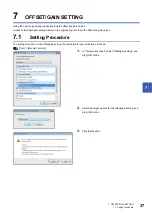
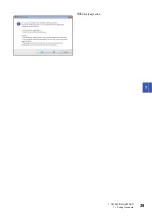
Page 41: ...7 OFFSET GAIN SETTING 7 1 Setting Procedure 39 7 13 Click Yes button ...
Page 47: ...I 45 MEMO ...
Page 51: ......


