background image

- 28 - 

change the mechanical home position.   

To use the sensor from the send returning, press                   


                [Home 

returning method since the second time returning] on the standard screen and set it ON. 


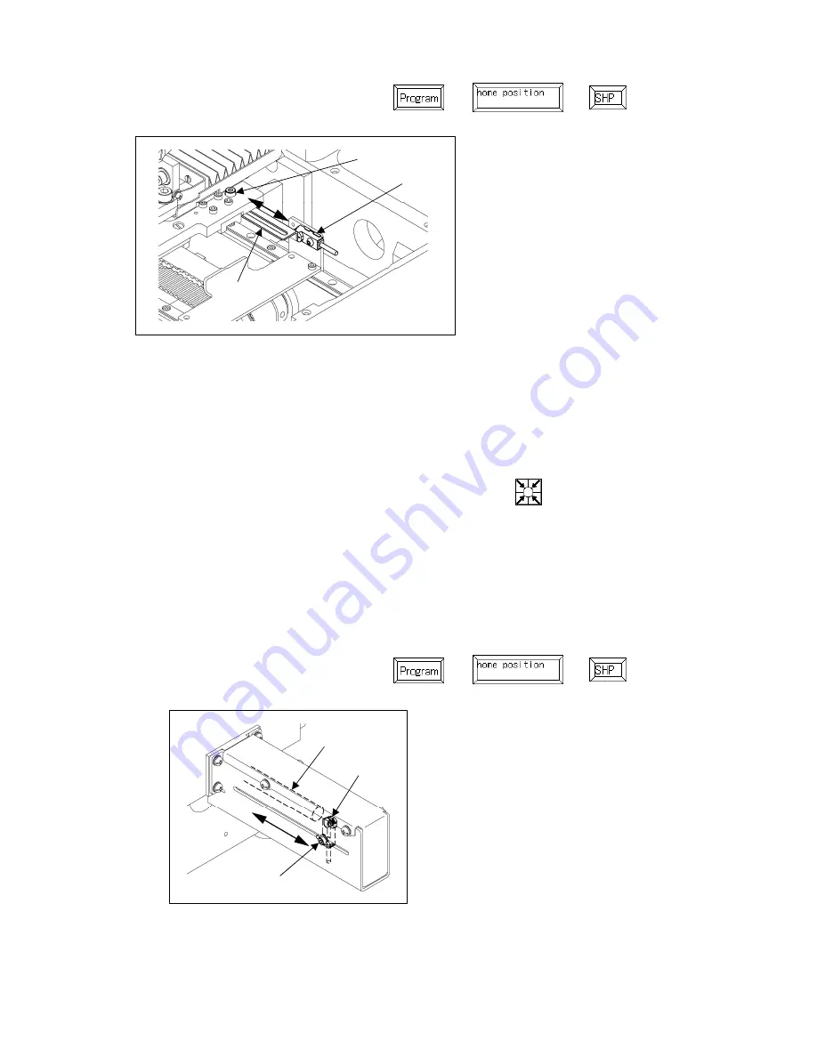
7-21-2. Adjustment of the Y direction 

(1)  Turn the power switch off. 

(2)  The mechanical home position of the Y direction is the position where the detector (No.2) can detect 

the edge of the Y drive (No.1).   

(3)  For the adjustment of the Y direction mechanical home position, loosen the detector set screw (No.3) 

then, move the detector to the arrow direction as shown on the figure. 

(4) Turn the power switch on. Press the home position return icon      , and check the mechanical 

home position. 

(5)  If the mechanical home position is not the desired position, carry out the same procedure (3) and (4) 

again. In that case, turn the power switch off each time. 

[Notice] The machine has a function that the motor memorizes the home position at the first home 

position returning operation after the switch is turned on. Therefore, from the second home position 

returning, it does not use the home position return sensor. Make sure to turn the power switch off to 

change the mechanical home position.   

To use the sensor from the send returning, press                   


                [Home 

returning method since the second time returning] on the standard screen and set it ON. 


7-22. The X-Y drive timing belt tension 

The X-Y drive timing belt tension is as follows as the factory default setting. 

X : 150 (N) ± 10%    Y : 150 (N) ± 10%

<1>: Detector plate X 

<2>: Detector 

<3>: Detector plate set screw


<1>: Y drive 

<2>: Detector 

<3>: Detector set screw


<3> 

<2> 

<1> 

<2> 

<1> 

<3> 

Summary of Contents for PLK-G1010

Page 1: ...Industrial Sewing Machine TECHNICAL MANUAL SEWING MACHINE HEAD Electronic Pattern Sewing Machine Model PLK G1010 A180E593P03 ...

Page 2: ...the instructions of both levels because they are important to personal safety CAUTION INDICATIONS No Caution indication Description 1 Precaution for sewing machine operation Indicates that removing the safety and operating the sewing machine for some other purposes with power on are prohibited z Please do not operate the sewing machine without protective equipment such as a needle guard an eye gua...

Page 3: ...e fixed power voltage 8 In the place where the power source cannot supply enough voltage to keep the motor running 9 In the place filled with strong electric noises such as high frequency welders INSTALLATION 1 Please have some specialists who have enough experience for the sewing machine installations install the sewing machine 2 Please have a qualified electrician perform necessary electric wiri...

Page 4: ... the reach of children who may drink oil by mistake 6 Please make sure to turn the power switch off before threading a needle 7 Before starting the sewing please make sure the position and the function of the halt switch 8 Please do not touch the operating parts during sewing operation 9 It is very dangerous to operate the sewing machine without safety guards eye guards belt covers link covers fin...

Page 5: ... 9 Installation of the eye guard 3 10 Connection of the electric cables 3 11 Installation of the thread stand 3 12 Installation of the chain for manual work holder presser 3 13 Installation of the spindle motor 3 4 4 4 4 5 5 6 6 7 8 8 9 4 LUBRICATION 10 5 PROPER OPERATION 10 5 1 Initial setting of the control box 5 2 Installation of the needle 5 3 Threading the upper thread 5 4 Winding the bobbin ...

Page 6: ...of the wiper 7 13 Adjustment of the work holder the adjustment for holding thick sewing material 7 14 Adjustment of the trimmer cam follower 7 15 Adjustment of the position of movable knife 7 16 Adjustment of the fixed knife position 7 17 Adjustment of the thread take up spring 7 18 Adjustment of the thread tail after the trimming 7 19 Adjustment of the upper thread tension release the width betwe...

Page 7: ... machine consists of the following main parts 1 Sewing machine head 2 Main shaft motor 3 Halt switch 4 Control box 5 Operation panel 6 Work holder foot switch 7 Start foot switch 8 Work holder pedal 9 Steel stand 10 Thread stand 11 Gas spring Option 1 2 4 5 7 9 11 10 6 8 3 ...

Page 8: ...Hook Large size shuttle hook Bobbin case With non racing spring Bobbin Aluminum bobbin Thread trimmer system Horizontal engagement with fixed knife and movable knife Lubrication system Replenishment with the oil braids from the oil tanks Lubrication oil Pulley SF oil X Y drive system Stepping motor feedback control Timing belt drive system Machine dimensions 1 200 mm W 867 mm L 1 289 mm H Weight T...

Page 9: ...and the steel stand are not MITSUBISHI original the table and the steel stand have to be strong enough to withstand the weight and Vibration of the sewing machine 6 When fitting the caster to the steel stand that are not MITSUBISHI original the caster with locking function has to be strong enough to withstand the weight and Vibration of the sewing machine 3 1 Preparation of the table 1 If the tabl...

Page 10: ...peration panel Connect the operation panel PLK G PAL with the CON A on the rear of the control box See page 7 for the location 3 5 Installation of the power switch and foot switch 1 Mount the power switch No 1 with the wood screw No 2 at the position as shown on the figure 2 Hook up the connector No 3 of the power switch to the control box CON B 3 Attach the power plug No 5 to the incoming electri...

Page 11: ... stand 3 When tilting the sewing machine the work clamp slides toward the hinges Remember to move the work clamps Fully to the right side of the casting before placing the sewing head in the sewing position 1 Put the machine head carefully on the damper cushion 2 Insert the hinge shafts No 1 into the hole on the machine then fix it to the machine with set screws No 2 3 Fit the hinge rubbers No 4 a...

Page 12: ... eye guard unit No 1 then mount the SW PW screws No 3 to the flat place of the sewing machine with the open guard 2 Return the open guard to the initial position then tighten the SW MW screws No 2 1 Hinge shaft two shafts 2 Set screw two screws 3 Hinge two hinges 4 Hinge rubber two rubbers 5 Support plate two plates 6 Socket bolt four bolts 7 Flat washer four washers 8 Head rest 9 Safety socket bo...

Page 13: ...me please check whether the cables are not pulled when tilting the sewing machine 1 3 6 7 5 4 2 CON A CON E CON F CON G CON H CON J CON B CON C CON D CON K 1 Solenoid cable 2 Solenoid power cable 3 Spindle encoder cable 4 Spindle motor cable 5 X Y spindle encoder cable 6 X Y spindle motor cable 7 P F spindle motor cable CON A Operation panel CON B Power supply CON C Various solenoid DC power CON D...

Page 14: ...head arm No 1 and the pedal No 2 on the stand side with the chain No 3 Notice Please make sure to unfasten the chain when tilting the machine Tilting the machine head linked with the chain causes the chain to be burst or the like 1 12 3 4 6 7 8 9 2 10 11 5 13 1 Upper column pipe 2 Lower column pipe 3 Spool stand base two stand bases 4 Spool mat two mats 5 Spool holder two holders 6 Spool shaft two...

Page 15: ...upling No 4 Use the part measuring 7mm on the gauge No 5 Position Bolt A No 6 in the UP position when reinstalling the coupling to the machine top shaft 4 Slip the gauge No 5 in between the needle bar and the needle plate Use the part of S side 50 1mm on the gauge 5 Be careful not to make the motor turn and fit the coupling to the upper shaft and then tighten the bolt A No 6 first and the bolt B N...

Page 16: ...he oil tanks are set at three places of the machine Pour oil through the oil holes of No 1 to No 3 to the oil tanks 2 The oil tanks have level marks at the center of the tank Running out the oil may cause the machine to make abnormal noise and seize up When the amount of oil decreases to one third or less than one third make sure to fill the tank with oil 5 PROPER OPERATION 5 1 Initial setting of ...

Page 17: ...Loosen the set screw No 1 then insert a new needle No 2 until the needle head is reached the end of the hole of the needle bar No 3 2 Tighten the set screw No 1 with facing the needle groove No 4 to the front 5 3 Threading the upper thread CAUTION 1 Please turn the power switch off when threading a needle Thread the upper thread as shown on the figure 3 1 2 4 1 Set screw 2 Needle 3 Needle bar 4 Ne...

Page 18: ...n the start switch second so that the thread continues winding to the bobbin while the start switch is stepped on 3 When the bobbin finishes winding a certain amount 80 to 90 of the outside diameter of bobbin of thread the bobbin presser arm is returned to the initial position Adjust the amount of the winding thread with the subsidiary arm No 4 4 To wind the bobbin thread during the sewing operati...

Page 19: ... If the pin starts rotating to the opposite direction turn the bobbin over and reset the bobbin 5 6 Setting the bobbin case 1 Pull the bobbin thread about 2 5cm out of the thread hole of the bobbin case 2 Open the cylinder cover No 1 3 Open the bobbin case latch No 2 and hold it then fit it securely in the shuttle hook No 3 4 2 1 3 5 1 Bobbin case 2 Bobbin 3 Thread 4 Bobbin case slit 5 Bobbin case...

Page 20: ...from The screen as default setting is set to the reading from internal memory mode The mode display at the left top on the screen is Press the when switching the reading from the internal memory to the reading from USB memory mode Pressing the also can switch the target Press the to switch the page with full of data 5 Select a data then set the data Press the target data number then press the 6 Se...

Page 21: ...bobbin thread tension Adjust the bobbin thread tension with the thread tension adjusting screw No 2 on the bobbin case No 1 The thread tension becomes loose when loosening the thread tension adjusting screw No 2 counterclockwise and the thread tension becomes tight when tightening the thread tension adjusting screw clockwise 2 Adjustment of upper thread tension Adjust the upper thread tension corr...

Page 22: ...g mark A is not matched to the needle bar bushing bottom line remove the rubber plug No 3 from the face plate then loosen the needle bar holder set screw No 4 4 For the needle class DP 5 move the needle bar to the position where the needle bar timing mark B is matched to the needle bar bushing bottom line 7 2 Adjustment of the position between the needle and the shuttle hook 1 Turn the power switc...

Page 23: ...described in 1 to 4 of above paragraph 7 2 2 Set the clearance between the shuttle hook No 1 point and the needle No 2 in 0 05 to 0 1mm standard position 3 Loosen the shuttle race set screw No 3 and turn the eccentric pin No 4 to move the hook entirely back and forth for adjustment Adjust the clearance to be standard 7 4 Adjustment of the clearance between the driver and the needle 1 Take the same...

Page 24: ...is time make sure that there is a clearance between the hook retainer and the shuttle race thread guide No 6 at least the thread can be passed through The standard clearance is 0 8mm The wide clearance causes the trimming failure 4 After the adjustment assemble the place with the reverse procedure Make sure to set the sliding plate No 5 at this time so that the needle No 11 comes down to the cente...

Page 25: ... factory default 1 Remove the cover No 1 and loosen the set screw A No 3 and B No 4 of the eccentric cam No 2 2 Keep the thread take up lever at the highest position then adjust the eccentric cam angle so that set screw B No 4 is positioned half size upper from the center line of the upper shaft shown on the lower right figure Retighten the set screws No 3 No 4 3 Turn the pulley by hand to check t...

Page 26: ...Presser foot lifting lever 5 Turn the power switch on then press the home position return icon 6 Check the clearance between the presser bar holder No 2 and the arm with the 41mm part on the gauge No 3 Refer to the next figure 7 If the clearance is less than 41mm loosen the detector plate set screw No 7 on the presser foot drive motor No 6 and adjust the notch part of detector plate No 8 To fix th...

Page 27: ...d then tighten the screw No 1 5 The correction value is set at 3 as the factory default 1 When changing the correction value at 0 an error message M 096 OVER LIMIT OF PRESSER FOOT STROKE may show up This happens when the presser foot stroke is already set to the sewing data and by changing the correction value the stroke in sewing data becomes 0mm or less In that case make new sewing data without ...

Page 28: ...the screw hole A and adjust with the method 2 described above 4 To adjust the walk in 4 to 10mm connect the link No 2 shown on the figure and adjust the method 2 described above 7 11 Adjustment of the presser foot spring pressure The presser foot spring pressure can be changed with the following two methods 1 To increase the spring pressure remove the face cover and loosen the bolt No 1 then adjus...

Page 29: ... 13 Adjustment of the work holder the adjustment for holding thick sewing material 1 If the sewing material No 1 is thick and the work holder does not press the sewing material strong enough adjust the work holder No 2 as follows 2 Turn the power switch on and insert the sewing material under the work holder then lower the work holder with the work holder foot switch 3 Loosen the set screws No 3 a...

Page 30: ...m follower arm 7 When loosening the adjust screw No 5 to the point a shown on the figure the cam follower arm No 1 goes back to the position in the direction B Loosen the nut No 4 from the point a to b 90 degree turns and then fix the adjust screw No 5 7 15 Adjustment of the position for movable knife 1 Tilt the sewing machine head and open the cylinder cover 2 Check the movable knife No 1 whether...

Page 31: ...read tension regulator No 3 then adjust the thread take up spring No 1 stroke to be in 9 to 10mm which is standard stroke 2 Insert the screw driver into the slit of the thread tension regulator and adjust the thread take up spring tension When tightening the screw driver clockwise the thread take up spring tension becomes tight and when loosening the screw driver counterclockwise the thread take u...

Page 32: ...w direction as shown on the figure When moving the upper thread tension release to the direction A the width between the discs becomes bigger 7 20 Adjustment of the opening time of the upper thread tension release disks When the presser foot rises the thread tension disks are open for a given length of time and close The default setting is set at one minute intervals To change the set value carry ...

Page 33: ... detector No 2 can detect the edge of the detector plate X No 1 4 For the adjustment of the X direction mechanical home position loosen the detector plate set screws No 3 at the left and right side then move the detector plate X in the arrow direction as shown on the figure Set the clearance between the detector plate X and the detector within the range of 1 0 to 1 5mm 5 Turn the power switch on P...

Page 34: ...anical home position is not the desired position carry out the same procedure 3 and 4 again In that case turn the power switch off each time Notice The machine has a function that the motor memorizes the home position at the first home position returning operation after the switch is turned on Therefore from the second home position returning it does not use the home position return sensor Make su...

Page 35: ...he threading parts or the hooks area regularly 2 The dust or the like sticking the X Y slide guide absorbs lubrication oil on the rails and significantly lowers the slide guide running life Clean the slide guide regularly and also pour some grease Recommended grease Multemp PS2 Produced by Kyodo Yushi Co Ltd Lithium grease 2 8 2 Disposing of oil waste If the waste oil pan is full filled in the oil...

Page 36: ...d tension is too tight Adjust thread tension 6 3 Parts on needle plate and presser foot touching thread are damaged Buff parts or change parts Thread tail is short Adjust thread tail with pre tension 7 18 Upper thread is pulled from needle hole when starting sewing Thread take up spring tension is too much Adjust thread take up spring tension 7 17 Frequent skip stitching happens Clearance between ...

Page 37: ...ion 7 5 Needle thread is too long Adjust needle thread with pre tension 7 18 All switches do not work after turning power on Tilting detect switch is kept on Check tilting detect switch 3 8 Work holder does not fall Foot switch is broken Change foot switch Sewing material is too thick Adjust work holder for thick material 7 13 Wiper system does not work Wiper hits needle or presser foot Adjust wip...

Page 38: ...2 APPENDIX MEMO If the steel stand is not MITSUBISHI original produce the parts with reference to the following drawings The drawings show the measurements of original MITSUBISHI stand parts 2 1 3 5 6 4 7 ...

Page 39: ... 33 Stand part 1 thickness 2mm Stand part 2 thickness 2mm ...

Page 40: ... 34 Stand part 3 thickness 2mm Stand part 4 thickness 2mm Stand part 5 thickness 2mm Stand part 6 rubber thickness 2 5m Stand part 7 permissible load more than 40kg per wheel ...

Page 41: ...SUBISHI ELECTRIC CORPORATION FACTORY AUTOMATION SYSTEM GROUP 2 7 3 Marunouchi Chiyoda ku Tokyo 100 8310 Japan Fax 81 3 3218 6821 New publication effective JAN 2009 Contents subject to change without notice ...

Reviews: