

EN-8
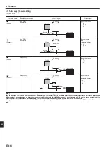
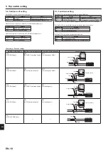
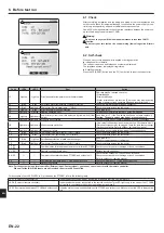
Parts name
Requirement
3-way valve
Connect a 3-way valve via relay.
Current: 0.5A Max. , 10mA Min.
Power supply: 230V AC
Connect the surge absorber according to the load at site.
Flow switch
It is required to protect system from the effects of insufficient flow.
Flow sensor
It is required to detect an error in flow rate. (The operation is validated with SIKA VVX20.)
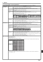
Strainer /Magnetic filter
(water circuit)
Provide it as required to protect parts from damages caused by iron particles/water/contamination (e.g. the position before pump and return part
from emitters).
Pressure relief valve
(Primary circuit side)
(Sanitary water side)
It is required to protect system from reaching high pressure.
Select the operating pressure depending on water pressure in the circuit in normal use.
* Follow the national regulations.
Expansion Vessel (Primary circuit side)
Expansion Vessel (Sanitary water side)
When the water circuit is closed, select the expansion vessel according to water quantity of the water circuit.
* Follow the national regulations.
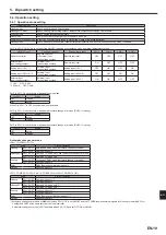
Limits of TOTAL electric current when con-
necting field supply parts
(Power supply from outdoor unit)
TOTAL current requirement MUST be 3A (otherwise, the fuse on the outdoor unit PCB will blow).
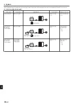
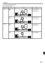
3. System
4. Electrical work
Power
supply
~/N
230V
50Hz
Earth
leakage
circuit
breaker
Wiring
circuit
breaker
or
Isolating
switch
L
N
S1
S2
S3
Outdoor unit
S1
S2
S3
TB6
To control
board
FTC2BR
FTC2BR
L
N
S1
S2
S3
TB6
L
N
Power
supply
3N~
400V
50Hz
Earth
leakage
circuit
breaker
Wiring
circuit
breaker
or
Isolating
switch
L3
L2
L1
N
S1
S2
S3
Outdoor unit
To control
board
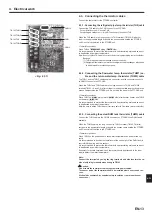
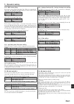
INPUT
Remote controller
Thermistor
OUTPUT
Power cables
CN401
(WH)
CN1A
(WH)
CNS2
(RD)
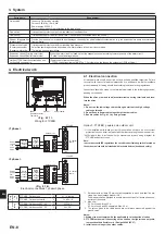
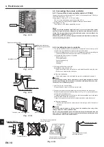
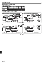
4.1. Electrical connection
All electrical work should be carried out by a suitably qualified technician. Failure
to comply with this could lead to electrocution, fire, and death. It will also invalidate
product warranty. All wiring should be according to national wiring regulations.
Connections should be made to the terminals indicated in the following figures de
-
pending on the phase.
When the wires are wired to adjacent terminals use ring terminals and insu-
late the wires.
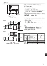
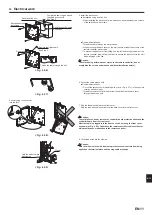
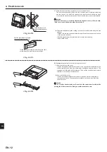
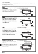
Option 1: FTC2BR powered via outdoor unit
<Fig. 4.1.2>
Electrical connections 1 phase/3 phase
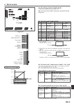
*1. A breaker with at least 3.0 mm contact separation in each pole shall be pro-
vided. Use earth leakage breaker (NV).
The breaker shall be provided to ensure disconnection of all active phase con-
ductors of the supply.
*2. Max. 45 m
If 2.5 mm² used, Max. 50 m
If 2.5 mm² used and S3 separated, Max. 80 m
*3. The values given in the table above are not always measured against the
ground value.
Notes:
1. Wiring size must comply with the applicable local and national codes.
2. FTC2BR/outdoor unit connecting cords shall not be lighter than polychlo
-
roprene sheathed flexible cord. (Design 60245 IEC 57)
3. Install an earth longer than other cables.
*1 If the installed earth leakage circuit breaker does not have an over-current
protection function, install a breaker with that function along the same power line.
*2 Affix label A that is included with the manuals near each wiring diagram for
FTC2BR and outdoor units.
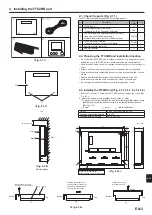
<Fig. 4.1.1>
Wiring for FTC2BR
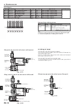
Note:
In accordance with IEE regulations the circuit breaker/isolating switch located on
the outdoor unit should be installed with lockable devices (health and safety).
Notes:
1. Do not run the low voltage cables through a slot that the high voltage
cables go through.
2. Do not bundle power cables together with other cables.
3. Bundle cables as Fig. 4.1.1 by using clamps.
<1 phase>
<3 phase>
Wiring
Wiring No.
× size (mm²)
FTC2BR - Outdoor unit
*2
3 × 1.5 (polar)
FTC2BR - Outdoor unit earth
*2
1 × Min. 1.5
Circuit rating
FTC2BR - Outdoor unit S1 - S2
*3
230V AC
FTC2BR - Outdoor unit S2 - S3
*3
24V DC
en
Summary of Contents for PAC-IF033B-E
Page 35: ......


