Mitsubishi Electric MELSERVO MR-J4-B-LL Series Instruction Manual Download Page 51

3. PARAMETERS 

3 -  6 

 
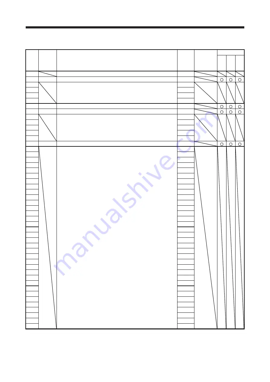
3.1.4 I/O setting parameters ([Pr. PD_ _ ]) 

No. Symbol 

Name 

Initial 
value 

Unit 

Control mode 

Position 

Speed 

Pr

essur

PD01 


For manufacturer setting 

0000h 


PD02 

*DIA2 

Input signal automatic on selection 2 

0000h 


PD03  For manufacturer setting 

0020h 


PD04  

0021h 

PD05  

0022h 

PD06  

0000h 

PD07 

*DO1 

Output device selection 1 

0005h 


PD08 

*DO2 

Output device selection 2 

0004h 


PD09  For manufacturer setting 

0003h 


PD10  

0000h 

PD11  

0004h 

PD12  

0000h 

PD13  

0000h 

PD14 

*DOP3  Function selection D-3 

0000h 


PD15  For manufacturer setting 

0000h 


PD16  

0000h 

PD17  

0000h 

PD18  

0000h 

PD19  

0000h 

PD20  

PD21  

PD22  

PD23  

PD24  

0000h 

PD25  

0000h 

PD26  

0000h 

PD27  

0000h 

PD28  

0000h 

PD29  

0000h 

PD30  

PD31  

PD32  

PD33  

0000h 

PD34  

0000h 

PD35  

0000h 

PD36  

0000h 

PD37  

0000h 

PD38  

0000h 

PD39  

0000h 

PD40  

0000h 

PD41  

0000h 

PD42  

0000h 

PD43  

0000h 

PD44  

0000h 

PD45  

0000h 

PD46  

0000h 

PD47  

0000h 

PD48  

0000h 


Summary of Contents for MELSERVO MR-J4-B-LL Series

Page 1: ...nual uses recycled paper MODEL MODEL CODE General Purpose AC Servo MR J4 _B_ LL SERVO AMPLIFIER INSTRUCTION MANUAL HEAD OFFICE TOKYO BLDG MARUNOUCHI TOKYO 100 8310 MODEL SERVO AMPLIFIER MR J4 _B_ LL SSCNET H Interface AC Servo for Pressure Control SERVO AMPLIFIER INSTRUCTION MANUAL MODEL DRIVE UNIT MR J4 DU_B_ LL ...

Page 2: ... or severe injury CAUTION Indicates that incorrect handling may cause hazardous conditions resulting in medium or slight injury to personnel or may cause physical damage Note that the CAUTION level may lead to a serious consequence depending on conditions Please follow the instructions of both levels because they are important to personnel safety What must not be done and what must be done are ind...

Page 3: ...electric shock be sure to connect the protective earth PE terminal marked of the servo amplifier to the protective earth PE of the cabinet To avoid an electric shock insulate the connections of the power supply terminals 2 To prevent fire note the following CAUTION Install the servo amplifier servo motor and regenerative resistor on incombustible material Installing them directly or close to combu...

Page 4: ...servo amplifier and servo motor which have been damaged or have any parts missing Do not block the intake and exhaust areas of the servo amplifier Otherwise it may cause a malfunction As the servo amplifiers and the servo motors are delicate products avoid dropping or heavy impact When you keep or use the equipment please fulfill the following environment Item Environment Ambient temperature Opera...

Page 5: ... Otherwise the servo amplifier will malfunction and will not output signals disabling the emergency stop and other protective circuits DOCOM Control output signal Servo amplifier RA For sink output interface 24 V DC DOCOM Control output signal 24 V DC Servo amplifier RA For source output interface When the wires are not tightened enough to the terminal block the wires or terminal block may generat...

Page 6: ... the power off etc before performing corrective actions Otherwise it may cause an accident If it is assumed that a power failure or product malfunction may result in a hazardous situation use a servo motor with an electromagnetic brake or provide an external brake system for holding purpose to prevent such hazard Configure an electromagnetic brake circuit which is activated by an external emergenc...

Page 7: ... which stores parameter settings etc is limited to 100 000 If the total number of the following operations exceeds 100 000 the servo amplifier may malfunction when the EEP ROM reaches the end of its useful life Write to the EEP ROM due to parameter setting changes Write to the EEP ROM due to device changes STO function of the servo amplifier The servo amplifier complies with safety integrity level...

Page 8: ...R55K_ converter unit This Instruction Manual does not describe the following items The following are the same as those for MR J4 _B Servo amplifiers For the details of the items refer to each chapter section indicated in the detailed explanation field MR J4 _B_ means MR J4 _B_ RJ Servo Amplifier Instruction Manual MR J4 _DU_ means MR J4 DU_ RJ MR CR55K_ Instruction Manual Item Detailed explanation...

Page 9: ...A 8 MEMO ...

Page 10: ... explanation of interfaces 2 12 2 5 3 Source I O interfaces 2 14 3 PARAMETERS 3 1 to 3 18 3 1 Parameter list 3 1 3 1 1 Basic setting parameters Pr PA_ _ 3 2 3 1 2 Gain filter setting parameters Pr PB_ _ 3 3 3 1 3 Extension setting parameters Pr PC_ _ 3 4 3 1 4 I O setting parameters Pr PD_ _ 3 6 3 1 5 Extension setting 2 parameters Pr PE_ _ 3 7 3 1 6 Extension setting 3 parameters Pr PF_ _ 3 8 3 1...

Page 11: ...ustment of pressure loop gain 4 4 4 6 Checking of adjustment result 4 7 5 TROUBLESHOOTING 5 1 to 5 8 5 1 Explanations of the lists 5 1 5 2 Alarm list 5 2 5 3 Warning list 5 5 5 4 Remedies for alarms 5 6 5 5 Remedies for warnings 2 7 6 OPTIONS AND PERIPHERAL EQUIPMENT 6 1 to 6 2 6 1 MR Configurator2 6 2 6 1 1 Specifications 6 2 APPENDIX App 1 to App 1 App 1 Optional data monitor function App 1 ...

Page 12: ...s which require pressure control Position control speed control and pressure control modes are available and the mode can be changed from the servo system controller Items not mentioned in this manual are the same as those for MR J4 _B_ servo amplifier Refer to MR J4 _B_ RJ Servo Amplifier Instruction Manual and MR J4 DU_ RJ MR CR55K_ Instruction Manual 1 Main difference from the MR J4 _B_ servo a...

Page 13: ...e function block diagram of the pressure control is shown below S Controller Position control Pressure control Note 1 Speed control Note 3 Note 2 Servo motor Control mode switchover Servo amplifier A D Position command Load cell Pressure command Speed limit command Speed limit command compensation Pr PT13 Pressure feedback offset Pr PT21 Load cell amplifier Analog monitor input filter setting Pr P...

Page 14: ...rvo Amplifier Instruction Manual Interface power supply Voltage DC 24 V 10 Current capacity A Note 1 0 3 including CN8 connector signals Control method Sine wave PWM control current control method Dynamic brake Built in External option Note 7 9 SSCNET III H communication cycle Note 6 0 222 ms 0 444 ms 0 888 ms Fully closed loop control Not available Scale measurement function Not available Load si...

Page 15: ...r effective load ratio 3 Test pulse is a signal which instantaneously turns off a signal to the servo amplifier at a constant period for external circuit to self diagnose 4 Except for the terminal block 5 The rated current is 2 9 A when the servo amplifier is used with a UL or CSA compliant servo motor 6 The communication cycle depends on the controller specifications and the number of axes connec...

Page 16: ...l computer or others MR Configurator2 compatible Encoder output pulses Not available Analog monitor Two channels Analog input Three points 10 V Digital I O DI 1 point DO 2 points Protective functions Overcurrent shut off regenerative overvoltage shut off overload shut off electronic thermal servo motor overheat protection encoder error protection regenerative error protection undervoltage protecti...

Page 17: ...r Failure to do so will cause an accident because the servo motor does not stop immediately but coasts at emergency stop Ensure the safety in the entire equipment For wiring of the external dynamic brake refer to section 11 17 of MR J4 _B_ RJ Servo Amplifier Instruction Manual 6 The external dynamic brake cannot be used for compliance with SEMI F47 standard Do not assign DB Dynamic brake interlock...

Page 18: ...ed loop control Not available Scale measurement function Not available Load side encoder interface Not available Communication function USB connection to a personal computer or others MR Configurator2 compatible Encoder output pulses Not available Analog monitor Two channels Analog input Three points 10 V Digital I O DI 1 point DO 2 points Protective functions Overcurrent shut off regenerative ove...

Page 19: ...e applicable when all I O signals are used The current capacity can be decreased by reducing the number of I O points 2 When closely mounting the servo amplifiers operate them at the ambient temperatures of 0 C to 45 C or at 75 or smaller effective load ratio 3 Test pulse is a signal which instantaneously turns off a signal to the servo amplifier at a constant period for external circuit to self d...

Page 20: ...nts 10 V Digital I O DI 1 point DO 2 points Protective functions Overcurrent shut off overload shut off electronic thermal servo motor overheat protection encoder error protection undervoltage protection instantaneous power failure protection overspeed protection and error excessive protection Functional safety STO IEC EN 61800 5 2 Safety performance Standards certified by CB EN ISO 13849 1 catego...

Page 21: ...rive unit Failure to do so will cause an accident because the servo motor does not stop immediately but coasts at emergency stop Ensure the safety in the entire equipment For wiring of the external dynamic brake refer to section 9 3 of MR J4 DU_ RJ MR CR55K_ Instruction Manual 6 The external dynamic brake cannot be used for compliance with SEMI F47 standard Do not assign DB Dynamic brake interlock...

Page 22: ...points 10 V Digital I O DI 1 point DO 2 points Protective functions Overcurrent shut off overload shut off electronic thermal servo motor overheat protection encoder error protection undervoltage protection instantaneous power failure protection overspeed protection and error excessive protection Functional safety STO IEC EN 61800 5 2 Safety performance Standards certified by CB EN ISO 13849 1 cat...

Page 23: ...otor does not stop immediately but coasts at emergency stop Ensure the safety in the entire equipment For wiring of the external dynamic brake refer to section 9 3 of MR J4 DU_ RJ MR CR55K_ Instruction Manual 6 The external dynamic brake cannot be used for compliance with SEMI F47 standard Do not assign DB Dynamic brake interlock in Pr PD07 and Pr PD08 Doing so will cause the drive unit to become ...

Page 24: ...UR series and HG RR series servo motors 1 200 V class Servo amplifier Servo motor HG KR HG MR HG SR HG UR HG RR HG JR HG JR When the maximum torque is 400 MR J4 10B LL 053 13 053 13 MR J4 20B LL 23 23 MR J4 40B LL 43 43 MR J4 60B LL 51 52 53 MR J4 70B LL 73 73 72 73 MR J4 100B LL 81 102 103 53 MR J4 200B LL 121 201 152 202 152 103 153 153 203 73 103 MR J4 350B LL 301 352 202 203 353 153 203 MR J4 ...

Page 25: ...K1M4 MR J4 22KB4 LL 20K14 25K14 22K1M4 3 100 V class Servo amplifier Servo motor HG KR HG MR MR J4 10B1 LL 053 13 053 13 MR J4 20B1 LL 23 23 MR J4 40B1 LL 43 43 1 5 Combinations of converter units drive units and servo motors 1 200 V class Servo motor Converter unit Drive unit HG JR 1000 r min series 1500 r min series MR CR55K MR J4 DU30KB LL 30K1 30K1M MR J4 DU37KB LL 37K1 37K1M 2 400 V class Ser...

Page 26: ...ng the pressure control mode do not set the vibration suppression control tuning mode to automatic setting with Pr PB02 MR J4 _B_ Section 7 1 5 Machine resonance suppression filter This filter function notch filter decreases the gain of the specific frequency to suppress the resonance of the mechanical system MR J4 _B_ Section 7 1 1 Shaft resonance suppression filter When a load is mounted to the ...

Page 27: ...ing a 1 phase 100 V AC 200 V AC for the input power supply will not comply with SEMI F47 standard Pr PA20 Pr PF25 MR J4 _B_ Section 7 4 Tough drive function This function makes the equipment continue operating even under the condition that an alarm occurs The tough drive function includes two types the vibration tough drive and the instantaneous power failure tough drive The vibration tough drive ...

Page 28: ...to other than the J4 mode standard control rotary servo motor Continuous operation to torque control mode This is not available with the MR J4 DU _B_ LL servo amplifier Lost motion compensation function This function improves the response delay occurred when the machine moving direction is reversed This is available with servo amplifiers with software version B4 or later Check the software version...

Page 29: ...5 MODEL 2 Model The following describes what each block of a model name indicates Not all combinations of the symbols are available a Servo amplifier Series Rated output SSCNET III H interface Symbol Rated output kW 10 0 1 20 0 2 40 0 4 60 0 6 70 0 75 100 1 200 2 350 3 5 500 5 700 7 11K 11 15K 15 22K 22 Power supply Symbol Power supply None 3 phase or 1 phase 200 V AC to 240 V AC 4 3 phase 380 V A...

Page 30: ...ower supply Symbol None Power supply c Drive unit 37K Symbol Power supply Series None 3 phase 200 V AC to 240 V AC 4 3 phase 380 V AC to 480 V AC Symbol Rated output kW 30K Rated output 37 Power supply SSCNET III H interface 45K 45 55K 55 30 Indicates drive unit Symbol Special specifications LL Pressure control type Special specifications ...

Page 31: ...1 FUNCTIONS AND CONFIGURATION 1 20 MEMO ...

Page 32: ...herwise the servo motor may operate unexpectedly resulting in injury Connect cables to the correct terminals Otherwise a burst damage etc may occur Ensure that polarity is correct Otherwise a burst damage etc may occur The surge absorbing diode installed to the DC relay for control output should be fitted in the specified direction Otherwise the emergency stop and other protective circuits may not...

Page 33: ...3 10 Grounding MR J4 _B_ section 3 11 MR J4 _DU_ section 3 7 2 1 Input power supply circuit CAUTION ALM Malfunction is not assigned by default Create a circuit that shuts off the main circuit by being interlocked with an alarm detected by the controller POINT When assigning ALM Malfunction to the CN3 9 pin set Pr PD08 to 0003 Items not mentioned in this section are the same as those for MR J4 _B_ ...

Page 34: ... 11 RA1 RA2 DOCOM DICOM 3 10 5 DICOM Note 14 Main circuit power supply Personal computer CN5 Note 5 MR Configurator2 USB cable MR J3USBCBL3M option Note 10 24 V DC Analog monitor 1 DC 10 V Analog monitor 2 DC 10 V MO1 LG MO2 4 1 14 SD Plate 2 m or less CN8 Note 15 Short circuit connector Packed with the servo amplifier 10 m or less 10 m or less 2 m or less Servo amplifier Note 3 4 Forced stop 2 No...

Page 35: ...n Manual for setting of axis selection 9 Make sure to cap the unused CN1B connector 10 Supply 24 V DC 10 to interfaces from outside The total current capacity of these power supplies must be 300 mA or lower 300 mA is the value applicable when all I O signals are used The current capacity can be decreased by reducing the number of I O points Refer to section 3 8 2 1 of MR J4 _B_ RJ Servo Amplifier ...

Page 36: ...2 DC 10 V 2 m or less CN8 Note 15 Short circuit connector Packed with the servo amplifier 10 m or less 2 m or less Note 3 4 Forced stop 2 Note 6 SSCNET III cable option Servo system controller CN1A CN1B Note 7 Note 1 Note 9 Cap CN1A CN1B The last servo amplifier Note 8 Note 6 SSCNET III cable option Note 7 24 V DC Note 10 Note 2 Analog monitor input 1 10 V Analog monitor input 2 10 V Pressure feed...

Page 37: ...fer to chapter 9 of MR J4 _B_ RJ Servo Amplifier Instruction Manual and chapter 7 of MR J4 DU_ RJ MR CR55K_ Instruction Manual CN5 USB connector Refer to section 6 1 CN3 The frames of the CN2 and CN3 connectors are connected to the protective earth terminal in the servo amplifier CN1A Connector for SSCNET III cable for previous servo amplifier axis CN1B Connector for SSCNET III cable for next serv...

Page 38: ...he forced stop deceleration MBR Electromagnetic brake interlock turns off without the forced stop deceleration 2 0 _ _ EM2 MBR Electromagnetic brake interlock turns off after the forced stop deceleration MBR Electromagnetic brake interlock turns off after the forced stop deceleration 0 1 _ _ Not using EM2 or EM1 MBR Electromagnetic brake interlock turns off without the forced stop deceleration 2 1...

Page 39: ...ake interlock DB When using the signal enable it by setting Pr PD07 and Pr PD08 When the dynamic brake needs to operate DB will turn off When using the external dynamic brake with the servo amplifier of 11 kW or more this device is required Refer to section 11 17 of MR J4 _B_ RJ Servo Amplifier Instruction Manual and section 9 3 of MR J4 DU_ RJ MR CR55K_ Instruction Manual For the servo amplifier ...

Page 40: ...P turns on to the point when it is accelerated again and has reached the off level is called hysteresis width Hysteresis width is 20 r min for this servo amplifier Limiting torque TLC When the torque reaches the torque limit value during torque generation TLC will turn on When the servo is off TLC will turn off Warning WNG When a warning occurs WNG will turn on When a warning is not occurring turn...

Page 41: ...pplication I O division Analog monitor 1 MO1 CN3 4 This signal outputs the data set in Pr PC09 to between MO1 and LG in terms of voltage Resolution 10 bits or equivalent Analog output Analog monitor 2 MO2 CN3 14 This signal outputs the data set in Pr PC10 to between MO2 and LG in terms of voltage Resolution 10 bits or equivalent Analog output 2 4 5 Power supply Signal name Symbol Connector pin No ...

Page 42: ... Servo amplifier USB D GND D 2 3 5 CN5 MBR DICOM Forced stop 2 Note 2 RA RA Isolated Note 3 24 V DC Note 3 24 V DC AD0 15 LG 11 AD1 19 AD2 12 Analog monitor input 1 10 V Analog monitor input 2 10 V Pressure feedback 10 V Note 2 Note 1 The signal cannot be used in the speed control mode and the pressure control mode 2 This diagram shows sink I O interface For source I O interface refer to section 2...

Page 43: ...igital output interface DO 1 This is a circuit in which the collector of the output transistor is the output terminal When the output transistor is turned on the current will flow to the collector terminal A lamp relay or photocoupler can be driven Install a diode D for an inductive load or install an inrush current suppressing resistor R for a lamp load Rated current 40 mA or less maximum current...

Page 44: ... LG SD Servo amplifier Approx 11 kΩ Input voltage 10 V 4 Analog output LG MO1 MO2 Servo amplifier Output voltage 10 V Note Maximum output current 1 mA Resolution 10 bits or equivalent Note Output voltage range varies depending on the output contents ...

Page 45: ...Switch For transistor EM2 etc Servo amplifier DICOM 2 Digital output interface DO 1 This is a circuit in which the emitter of the output transistor is the output terminal When the output transistor is turned on the current will flow from the output terminal to a load A maximum of 2 6 V voltage drop occurs in the servo amplifier ALM etc Note 24 V DC 10 300 mA If polarity of diode is reversed servo ...

Page 46: ...be written to each parameter Setting may not be made to some parameters and their ranges depending on the servo system controller model servo amplifier software version and MR Configurator2 software version For details refer to the servo system controller user s manual Check the software version of the servo amplifier with MR Configurator2 3 1 Parameter list POINT The parameter whose symbol is pre...

Page 47: ...n range 1600 pulse PA11 For manufacturer setting 1000 0 PA12 1000 0 PA13 0000h PA14 POL Rotation direction selection 0 PA15 For manufacturer setting 4000 PA16 1 PA17 0000h PA18 0000h PA19 BLK Parameter writing inhibit 00ABh PA20 TDS Tough drive setting 0000h PA21 AOP3 Function selection A 3 0001h PA22 For manufacturer setting 0000h PA23 DRAT Drive recorder arbitrary alarm trigger setting 0000h PA2...

Page 48: ...bration suppression control 1 Resonance frequency 100 0 Hz PB21 VRF13 Vibration suppression control 1 Vibration frequency damping 0 00 PB22 VRF14 Vibration suppression control 1 Resonance frequency damping 0 00 PB23 VFBF Low pass filter selection 0000h PB24 MVS Slight vibration suppression control 0000h PB25 BOP1 Function selection B 1 0000h PB26 CDP Gain switching function 0000h PB27 CDL Gain swi...

Page 49: ...9 VRF24B Vibration suppression control 2 Resonance frequency damping after gain switching 0 00 PB60 PG1B Model loop gain after gain switching 0 0 rad s PB61 For manufacturer setting 0 0 PB62 0000h PB63 0000h PB64 0000h 3 1 3 Extension setting parameters Pr PC_ _ No Symbol Name Initial value Unit Control mode Position Speed Pressure PC01 ERZ Error excessive alarm level 0 rev PC02 MBR Electromagneti...

Page 50: ...ount 0 0 0001rev PC32 For manufacturer setting 0000h PC33 0 PC34 100 PC35 0000h PC36 0000h PC37 0000h PC38 ERW Error excessive warning level 0 rev PC39 For manufacturer setting 0000h PC40 0000h PC41 0000h PC42 0000h PC43 0000h PC44 0000h PC45 0000h PC46 0000h PC47 0000h PC48 0000h PC49 0000h PC50 0000h PC51 0000h PC52 0000h PC53 0000h PC54 0000h PC55 0000h PC56 0000h PC57 0000h PC58 0000h PC59 000...

Page 51: ...D08 DO2 Output device selection 2 0004h PD09 For manufacturer setting 0003h PD10 0000h PD11 0004h PD12 0000h PD13 0000h PD14 DOP3 Function selection D 3 0000h PD15 For manufacturer setting 0000h PD16 0000h PD17 0000h PD18 0000h PD19 0000h PD20 0 PD21 0 PD22 0 PD23 0 PD24 0000h PD25 0000h PD26 0000h PD27 0000h PD28 0000h PD29 0000h PD30 0 PD31 0 PD32 0 PD33 0000h PD34 0000h PD35 0000h PD36 0000h PD...

Page 52: ...0h PE28 0000h PE29 0000h PE30 0000h PE31 0000h PE32 0000h PE33 0000h PE34 1 PE35 1 PE36 0 0 PE37 0 00 PE38 0 00 PE39 20 PE40 0000h PE41 EOP3 Function selection E 3 0000h PE42 For manufacturer setting 0 PE43 0 0 PE44 LMCP Lost motion compensation positive side compensation value selection 0 0 01 PE45 LMCN Lost motion compensation negative side compensation value selection 0 0 01 PE46 LMFLT Lost mot...

Page 53: ...n selection F 5 0000h PF07 For manufacturer setting 0000h PF08 0000h PF09 0 PF10 0 PF11 0 PF12 DBT Electronic dynamic brake operating time 2000 ms PF13 For manufacturer setting 0000h PF14 10 PF15 0000h PF16 0000h PF17 0000h PF18 0000h PF19 0000h PF20 0000h PF21 DRT Drive recorder switching time setting 0 s PF22 For manufacturer setting 200 PF23 OSCL1 Vibration tough drive Oscillation detection lev...

Page 54: ...F43 0000h PF44 0 PF45 0000h PF46 0000h PF47 0000h PF48 0021h 3 1 7 Linear servo motor DD motor setting parameters Pr PL_ _ Linear servo motor DD motor setting parameters Pr PL_ _ are not used with MR J4 DU _B_ LL servo amplifiers Do not change from the default The default values are the same as those for MR J4 _B_ servo amplifiers To check the default values refer to section 5 1 7 of MR J4 _B_ RJ ...

Page 55: ...r manufacturer setting 0000h PT16 0000h PT17 0 PT18 0 PT19 0 PT20 0000h PT21 AFBO Pressure feedback offset 0 mV PT22 AFBD Pressure feedback unit constant 20000 Command unit PT23 AO1 Analog monitor input 1 offset 0 mV PT24 AD1 Analog monitor input 1 unit constant 20000 Command unit PT25 AO2 Analog monitor input 2 offset 0 mV PT26 AD2 Analog monitor input 2 unit constant 20000 Command unit PT27 ADF ...

Page 56: ... PA_ _ No Symbol Name and function Initial value unit Setting range PA14 POL Rotation direction selection Select the rotation direction of command input pulse 0 0 to 1 Setting value Servo motor rotation direction Positioning address increase Positioning address decrease 0 CCW CW 1 CW CCW For the pressure control mode the servo motor rotation direction and the pressure increasing direction are as f...

Page 57: ...ter 2 in case that the vibration exceeds the value of the oscillation level set in Pr PF23 For details refer to section 7 3 of MR J4 _B_ RJ Servo Amplifier Instruction Manual This cannot be used in the pressure control mode 0h _ x _ _ SEMI F47 function selection 0 Disabled 1 Enabled Selecting 1 enables to avoid triggering AL 10 Undervoltage using the electrical energy charged in the capacitor in c...

Page 58: ...1 _ _ 08 Servo motor side droop pulses 10 V 10000 pulses Note 1 _ _ 09 Servo motor side droop pulses 10 V 100000 pulses Note 1 _ _ 0A Feedback position 10 V 1 Mpulse Note 1 _ _ 0B Feedback position 10 V 10 Mpulses Note 1 _ _ 0C Feedback position 10 V 100 Mpulses Note 1 _ _ 0D Bus voltage 200 V class and 100 V class 8 V 400 V 400 V class 8 V 800 V _ _ 0E Speed command 2 8 V max speed _ _ 17 Interna...

Page 59: ... Extension setting 3 parameters Pr PF_ _ Details of Extension setting 3 parameters Pr PF_ _ are the same as those for MR J4 _B_ servo amplifier Refer to section 5 2 6 of MR J4 _B_ RJ Servo Amplifier Instruction Manual and section 5 2 2 of MR J4 DU_ RJ MR CR55K_ Instruction Manual 3 2 7 Linear servo motor DD motor setting parameters Pr PL_ _ Linear servo motor DD motor setting parameters Pr PL_ _ a...

Page 60: ...tion and the pressure increasing direction are as follows with a combination of Rotation direction selection in Pr PT14 0h Parameter setting value Positioning address increase Positioning address decrease PT12 _ _ x _ PA14 Pressure Servo motor rotation direction Pressure Servo motor rotation direction 0 0 Decrease CCW Increase CW 1 CW CCW 1 0 Increase CCW Decrease CW 1 CW CCW This is available wit...

Page 61: ... is compensated by 100 mV 0 mV 9999 to 9999 PT22 AFBD Pressure feedback unit constant Set the conversion coefficient of the pressure feedback voltage to be returned to the controller Set a pressure feedback value to be returned to the controller at the maximum input voltage 10 V of AD0 Pressure feedback 20000 Command unit 500 to 30000 PT23 AO1 Analog monitor input 1 offset Set the offset voltage o...

Page 62: ...me constant for AD0 Pressure feedback Refer to table 3 2 for the filter time constant 0h _ _ x _ AD1 Analog monitor input 1 filter time constant Select the filter time constant for AD1 Analog monitor input 1 Refer to table 3 2 for the filter time constant 0h _ x _ _ AD2 Analog monitor input 2 filter time constant Select the filter time constant for AD2 Analog monitor input 2 Refer to table 3 2 for...

Page 63: ...3 PARAMETERS 3 18 MEMO ...

Page 64: ...Checking of adjustment result Start a system after installation and wiring Before executing the pressure control adjustment adjust GD2 Pr PB06 PG1 Pr PB07 PG2 Pr PB08 VG2 Pr PB09 and VIC Pr PB10 in the position control mode referring to chapter 6 and 7 of MR J4 _B_ RJ Servo Amplifier Instruction Manual Set the rotation direction the pressure increasing direction for positioning address and the for...

Page 65: ...es Set Pr PA14 Rotation direction selection to 0 When the pressure increases as the positioning address increases Set selection of pressure increasing direction for positioning address of Pr PT12 to pressure increases as the positioning address increases _ _ 1 _ Pressure control axis Chip When the setting of Pr PA14 or Pr PT12 is incorrect the machine may not operate properly such that the servo m...

Page 66: ...re feedback offset voltage with Pr PT 21 Pressure feedback offset When 100 is set the voltage is compensated by 100 mV When 100 is set the voltage is compensated by 100 mV 3 Setting of the pressure feedback input filter Set the low pass filter for removing noise from the pressure feedback input When the low pass filter is used the filter response frequency affects the response performance of the p...

Page 67: ...ional control gain pressure loop gain and the integral control gain pressure integral compensation and pressure incomplete integral coefficient If the result of the proportional control gain adjustment does not satisfy the required performance adjust the integral control gain 1 Parameters The following parameters are used for the gain adjustment of the pressure control Parameter Symbol Name PT01 A...

Page 68: ...tting value of Pr PT01 Changing Pr PT22 Pressure feedback unit constant also changes the response performance of the pressure control In this case readjust the pressure loop gain For example if the value of Pr PT22 is doubled it works the same as the pressure control proportional gain of Pr PT01 Pressure loop gain is doubled When the response performance of the pressure control needs to be unchang...

Page 69: ...n between the setting value of the integral control gain pressure integral compensation and pressure incomplete integral coefficient and the response performance Pr PT03 Pressure incomplete integral coefficient Setting value of Pr PT03 Large Low High Small Time Response Pressure Pressure command Pressure feedback Increasing the setting value of Pr PT03 improves track ability to the command A too l...

Page 70: ...PT03 Pressure incomplete integral coefficient Setting value of Pr PT03 Large Low High Small Time If the setting value of Pr PT03 is small the pressure does not reach to the command A too large setting value will generate overshoot Response Pressure Pressure command Pressure feedback Increasing the setting value of Pr PT03 Pr PT02 Pressure integral compensation Pressure command Pressure feedback De...

Page 71: ...4 PRESSURE LOOP GAIN ADJUSTMENT 4 8 MEMO ...

Page 72: ...No Name Detail No Detail name Indicates the alarm or warning No name detail No and detail name 2 Stop method For the alarms and warnings in which SD is written in the stop method column the servo motor stops with the dynamic brake after forced stop deceleration For the alarms and warnings in which DB or EDB is written in the stop method column the servo motor stops with the dynamic brake without f...

Page 73: ... error 1 DB 16 2 Encoder initial communication Receive data error 2 DB 16 3 Encoder initial communication Receive data error 3 DB 16 5 Encoder initial communication Transmission data error 1 DB 16 Encoder initial communication error 1 16 6 Encoder initial communication Transmission data error 2 DB 16 7 Encoder initial communication Transmission data error 3 DB 16 A Encoder initial communication Pr...

Page 74: ...ror 1 EDB 30 1 Regeneration heat error DB Note 1 Note 1 Note 1 30 Regenerative error 30 2 Regeneration signal error DB Note 1 Note 1 Note 1 30 3 Regeneration feedback signal error DB Note 1 Note 1 Note 1 31 Overspeed 31 1 Abnormal motor speed SD 32 1 Overcurrent detected at hardware detection circuit during operation DB 32 Overcurrent 32 2 Overcurrent detected at software detection function during...

Page 75: ...ve 52 3 Excess droop pulse 2 SD 52 4 Error excessive during 0 torque limit SD 52 5 Excess droop pulse 3 EDB 54 Oscillation detection 54 1 Oscillation detection error EDB 56 Forced stop error 56 2 Over speed during forced stop EDB 56 3 Estimated distance over during forced stop EDB 63 STO timing error 63 1 STO1 off DB 63 2 STO2 off DB 8A USB communication time out error 8A 1 USB communication time ...

Page 76: ...Absolute position counter warning E3 2 Absolute position counter warning E3 5 Encoder absolute positioning counter warning E4 Parameter warning E4 1 Parameter setting range error warning E6 Servo forced stop warning E6 1 Forced stop warning SD E7 Controller forced stop warning E7 1 Controller forced stop input warning SD E8 Cooling fan speed reduction warning E8 1 Decreased cooling fan speed warni...

Page 77: ...recorded in the alarm history Refer to this section and MELSERVO J4 Servo Amplifier Instruction Manual Troubleshooting to remove the cause of the alarm Use MR Configurator2 to refer to the cause of alarm occurrence Alarm No 3E Name Operation mode error Alarm content The operation mode setting was changed The control mode was mistakenly switched Detail No Detail name Cause Check method Check result...

Page 78: ...g AL E1 Overload warning 1 AL E2 Servo motor overheat warning AL EC Overload warning 2 Warnings except AL F0 Tough drive warning are not recorded in the alarm history If AL E6 AL E7 AL E9 AL EA or AL EB occurs the servo amplifier will be the servo off status If any other warning occurs operation can be continued but an alarm may occur and proper operation may not be performed Refer to this section...

Page 79: ...5 TROUBLESHOOTING 5 8 MEMO ...

Page 80: ...uction Manual MR J4 _DU_ means MR J4 DU_ RJ MR CR55K_ Instruction Manual Item Detailed explanation Cable connector sets MR J4 _B_ section 11 1 MR J4 _DU_ section 9 1 Regenerative option MR J4 _B_ section 11 2 MR J4 _DU_ section 9 2 FR BU2 H brake unit MR J4 _B_ section 11 3 MR J4 _DU_ section 9 10 FR RC H power regeneration converter MR J4 _B_ section 11 4 FR CV H power regeneration common convert...

Page 81: ...on a personal computer 6 1 1 Specifications Item Description Project Create read save delete project system setting and print Parameter Parameter setting Monitor Display all I O monitor graph and ABS data display Diagnosis Alarm display alarm onset data drive recorder no motor rotation Note system configuration life diagnosis machine diagnosis Note Test operation Jog operation positioning operatio...

Page 82: ...B_ LL Items not mentioned are the same as those for MR J4 _B_ servo amplifier Refer to app 13 1 of MR J4 _B_ RJ Servo Amplifier Instruction Manual Data type Description Pressure command The pressure command from the controller is displayed Load cell pressure A pressure feedback value of the load cell for pressure control is displayed Monitor input signal ch1 A value of the analog monitor input 1 i...

Page 83: ...on This manual confers no industrial property rights or any rights of any other kind nor does it confer any patent licenses Mitsubishi Electric Corporation cannot be held responsible for any problems involving industrial property rights which may occur as a result of using the contents noted in this manual 2016 MITSUBISHI ELECTRIC CORPORATION ...

Page 84: ...7 St Petersburg Russia Tel Fax 7 812 633 3497 7 812 633 3499 Sweden Mitsubishi Electric Europe B V Scandinavia Fjelievagen 8 SE 22736 Lund Sweden Tel Fax 46 8 625 10 00 46 46 39 70 18 Turkey Mitsubishi Electric Turkey A S Umraniye Branch Serifali Mahallesi Nutuk Sokak No 5 TR 34775 Umraniye Istanbul Turkey Tel Fax 90 216 526 3990 90 216 526 3995 UAE Mitsubishi Electric Europe B V Dubai Branch Duba...

Page 85: ...uct from our company viii any other failures which we are not responsible for or which you acknowledge we are not responsible for 2 Term of warranty after the stop of production 1 We may accept the repair at charge for another seven 7 years after the production of the product is discontinued The announcement of the stop of production for each model can be seen in our Sales and Service etc 2 Please...

Page 86: ...nual uses recycled paper MODEL MODEL CODE General Purpose AC Servo MR J4 _B_ LL SERVO AMPLIFIER INSTRUCTION MANUAL HEAD OFFICE TOKYO BLDG MARUNOUCHI TOKYO 100 8310 MODEL SERVO AMPLIFIER MR J4 _B_ LL SSCNET H Interface AC Servo for Pressure Control SERVO AMPLIFIER INSTRUCTION MANUAL MODEL DRIVE UNIT MR J4 DU_B_ LL ...

Reviews: