


3.3VB
3.3VB
2.5VS
5VB
3D-H
3D-Y
3D-Pb
3D-C
3D-Pr
3D-VID
3D-V
FREERUN
5VSCL
5VSDA
3DRST
22
23
24
25
26
27
28
29
30
51
52
53
54
55
56
57
58
59
60
61
62
63
64
65
66
67
68
69
70
71
72
73
74
75
76
77
78
79
80
81
82
83
84
85
86
87
88
89
90
91
92
93
94
95
96
97
98
99
VCCOUT
GND
U2-IN
A-PED
H-SYNC
CIN
V2-IN
X-358
V-SYNC
SGND2
VOUT
ADRS-9EH
CERA
SGND
CVBS/Y-IN
-B-Y_OUT
H-TIM
AFC
APC
SVCC[
U2-OUT
-R-Y_IN
Y2-OUT
SCL
-R-Y_OUT
SCP
SECAM-REF
SDA
Y2-IN
JGND
-B-Y_IN
V2-OUT
X-443/358
Y-OUT
CP-IN
JVCC
X-NTSC
IREF
UOUT
V-HOLD
ABLFILIN
V-TIM
EL 1881CSZ-T7
L2M71
27MH
0.1
C2M37
16V
1/16W
R2M37
47
22
C2M35
50V
0.1
C2M82
16V
0.1
C2M92
16V
L2M46
221 OHM
16V
C2M75
47
IC9M01-3.3VB
120
1/16W
R2M79
1/16W
R8H83
10K
15
C8H26
50V
16V
C9M08
47
47
C2M27
50V
3D-Pr
0.1
C2M01
16V
Q2M73
3D-Pb
22
C2M71
50V
X2M47
20.000MHz
L2M70
221 OHM
0.1
C2M32
16V
0.1
C2M65
16V
0.1
C8H25
16V
1U
C2M87
10V/16V
390
1/16W
R2M03
390
1/16W
R2M73
0.1
C2M57
16V
IC9M01-2.5V
Q2M32
0.1
C2M95
16V
1/16W
R2M42
330
0.1
C2M58
16V
IC9M02-GND
16V
C9M11
100
56K
1/16W
R2M74
0.1
C9M07
16V
C2M54
10
16V
16V
C2M44
47
560
C2M50
25V
4700
C8H39
50V
2SA1235A-T112-1E,F
Q2M50
12K
1/16W
R2M44
2SA1235A-T112-1E,F
Q8H21
1/16W
R8H38
100
C2M73
47
16V
0.1
C2M91
16V
L2M53
221 OHM
22
C2M72
50V
390
1/16W
R2M02
0.01
C8H02
25V/50V
2SC3052-T112-1E,F
Q2M44
16V
C9M33
47
0.1
C2M25
16V
22
C2M55
50V
5VSDA
0
1/16W
R2M01
820
C2M49
25V
1/16W
R8H80
100
3D-C
1/16W
R2M40
100
L8H25
221 OHM
0.1
C2M85
16V
1/16W
R8H39
220
C2M43
47
16V
1/16W
R8H36
100
L2M21
221 OHM
1/16W
R8T83
100
16V
C2M28
100
16V
C8H04
47
2SC3052-T112-1E,F
Q2M31
C2M80
47
16V
2SC3052-T112-1E,F
Q2M30
0.1
C2M94
16V
0.1
C2M24
16V
1/16W
R2M82
100
820
1/16W
R2M83
L2M45
221 OHM
L2M50
5.6MH
10K
1/16W
R8H84
X8H26
3.579545MHZ
L2M39
221 OHM
IC9M02-2.5VS
0.47
C8H34
10V
16V
C8H33
4.7
120
C8H21
50V
16V
C2M38
47
16V
C8H24
47
5VSCL
3D-VID
31
32
33
34
35
36
37
38
39
40
41
42
43
44
45
46
47
48
49
50
16V
C2M64
47
1/16W
R2M72
330
2SA1235A-T112-1E,F
Q2M71
0.1
C9M06
16V
1.5K
1/16W
R2M34
1/16W
R2M70
100
1.5K
1/16W
R2M22
0.1
C2M90
16V
820
1/16W
R2M55
390
1/16W
R2M71
0.1
C2M86
16V
220
1/16W
R2M51
330
1/16W
R8H01
2SA1235A-T112-1E,F
Q2M43
1/16W
R2M24
680K
56K
1/16W
R2M45
L2M35
15MH
0.47
C8H30
10V
1K
1/16W
R2M77
1/16W
R2M33
100
1U
C2M88
10V/16V
100
1/16W
R2M60
1K
1/16W
R2M78
16V
C2M98
10
16V
C8H01
4.7
L2M81
221 OHM
0.1
C2M52
16V
1/16W
R2M35
470
0.1
C2M70
16V
15
C2M30
50V
2SC3052-T112-1E,F
Q2M42
2SC3052-T112-1E,F
Q8H22
1.5K
1/16W
R2M38
0.1
C2M81
16V
1/16W
R2M50
56
IC9M02-3.3VB
L8H03
221 OHM
2SC3052-T112-1E,F
Q2M21
1/16W
R8T85
100
470
C8H27
25V/50V
3D-V
330
1/16W
R2M43
0.1
C2M53
16V
L2M40
221 OHM
3DRST
1K
1/16W
R2M52
300
1/16W
R2M36
1/16W
R8H37
100
22
C2M42
50V
22
C2M47
50V
22
C2M48
50V
120
1/16W
R2M53
0.47
C8H28
10V
1/16W
R2M21
100
2.2K
1/16W
R8H00
820
1/16W
R2M81
0.1
C2M21
16V
1/16W
R2M23
680
1
3
2
8.2K
1/16W
R8H02
12K
1/16W
R2M75
0.1
C2M96
16V
0.1
C8H03
16V
820
1/16W
R2M84
12
33
39
32
13
27
38
17
20
35
1
31
34
23
15
2
29
25
7
21
8
36
24
16
30
37
11
5
22
6
28
18
10
3
26
4
19
40
9
14
1/16W
R8H28
15K
1/16W
R2M54
100
100
1/16W
R2M59
1/16W
R2M57
10K
240
1/16W
R2M76
390
1/16W
R2M41
560
C2M22
25V
0.1
C2M45
16V
2SC3052-T112-1E,F
Q2M74
C2M89
47
16V
0.1
C2M78
16V
1/16W
R8H81
100
1U
C8H38
10V/16V
1/16W
R2M80
100
0.1
C2M34
16V
2SA1235A-T112-1E,F
Q2M41
CSB500F2
CF8H01
0.1
C2M74
16V
1/16W
R2M49
360
3D-H
1/16W
R2M48
1K
0.1
C2M23
16V
0.1
C2M99
16V
0
1/16W
R2M04
3D-Y
240
1/16W
R2M47
L2M41
27MH
330K
1/16W
R8H30
16V
C2M59
47
10K
1/16W
R8H04
0.47
C8H32
10V
1/16W
R2M46
220
0.1
C2M40
16V
0.047
C2M51
16V/25V
1/16W
R8H26
1.5K
FREERUN
1/16W
R8H82
100
1/16W
R8H34
75
Q2M72
C2M56
47
16V
L2M38
221 OHM
0.1
C2M46
16V
3.3K
1/16W
R8H21
8
VDD 5V
6
RSET
5
BUST/BACK PORCH OUTPUT
7
ODD/EVEN OUTPUT
4
GND
1
COMPOSITE SYNC OUT
2
COMPOSITE VIDEO IN
3
VERTICAL SYNC OUT
SIGNAL2
SIGNAL2
B8H
SIGNAL2
SIGNAL2
3.3VB
9VB
5VB
9VB
IC2M00
uPD64083GF-3BA-A
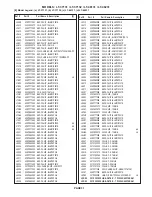
LT-46131 VLP33
LT-37131 VLP33
LT-46231 VLP33+
PAGE 5
LT-37132 VLP33+
CONTENTS
20
12
21
17
16
8
19
18
3
6
13
5
9
15
4
10
1
2
14
11
7
100
EXTDYCO1
TEST9
EXTDYCO2
TEST14
TEST13
TEST5
EXTDYCO0
EXTALTF
TESTIC2
TEST3
TEST10
TEST2
TEST6
TEST12
TEST1
TEST7
DGND
TESTIC1
TEST11
TEST8
TEST4
EXTDYCO3
EXTDYO04
EXTDYC05
EXTDYC06
EXTDYC07
EXTDYCO8
EXTDYCO9
DGNDRAM DGNDRAM
AGND
FSCI
AVDD
CKMD
DGND
CLK8
RSTB
SLA0
SCL
SDA
ST0
ST1
NSTD
DVDD
DYCO0
DYCO1
DYCO2
DYCO3
DYCO4
DYCO5
DYCO6
DYCO7
DYCO8
DYCO9
ALTF
CSI
RPLL
LINE
KIL
DGND
DVDDRAM
DVDDRAM
TEST15
TEST16
TEST17
TEST18
TEST19
DVDIO
TEST20
DGND
TEST21
TEST22
TEST23
TEST24
DVDD
AVDD
XI
XO
AGND
FSCO
AVDD
CBPC
ACO
AYO
CBPY
AGND
AGND
AYI
VCLY
CRBY
VRTY
AVDD
AVDD
VRTC
VRBC
ACI
AGND
TEST25
TEST26
DVDD
IC9M02
LD29150DT25R
IC8H01
CXA2019AQ/T4
IC2M02
PG 4.....SIGNAL2 [VIDEO SW / AUDIO AMP]
PG 6.....FRONT, E2P, AT-SW, PREAMP
PG 5.....SIGNAL3 [3DYC / NTSC DECODER]
PG 1.....BLOCK
PG 3.....SIGNAL1 [TERMINAL]
PG 2.....POWER
6
15
5
10
7
16
12
3
1
8
2
11
4
13
9
14
A
B
J
K
H
E
F
C
G
D
I
PG 5.....SIGNAL3 [3DYC / NTSC DECODER]
Summary of Contents for LT-37131
Page 2: ......
Page 4: ...MODELS LT 37131 LT 37132 LT 46131 LT 46231 Page 4 ...
Page 37: ...Page 37 MODELS LT 37131 LT 37132 LT 46131 LT 46231 POWER SUPPLY ...
Page 38: ...Page 38 MODELS LT 37131 LT 37132 LT 46131 LT 46231 DM SIGNAL POWER SUPPLIES ...
Page 39: ...Page 39 MODELS LT 37131 LT 37132 LT 46131 LT 46231 VIDEO SIGNAL PATH ...
Page 40: ...Page 40 MODELS LT 37131 LT 37132 LT 46131 LT 46231 AUDIO SIGNAL PATH ...


