background image

E

11

Connecting Peripheral Equipment

Other terminals

PC/AV audio output terminals

•  Audio from the equipment connected to the AV audio input 

terminals or PC audio input terminal is output. Connect to 
the audio input terminals of the connected equipment using 
a commercially available audio cable (RCA).

•  The audio output varies depending on the input mode 

selection. (See page 15.)

•  The volume level can be adjusted using the volume 

adjustment. (See page 15.)

•  Selecting FIXED of “AUDIO OUTPUT” from the OPTION 

menu 

fi

 xes the volume of sound output from the audio 

output terminals. (See page 19.)

•  Audio signals output from the PC/AV audio output terminals 

cannot be adjusted using the AUDIO menu.

PC/AV output terminals 

Video signals from PC1 and AV1 can be output to
HDCP-compatible external device. Use this terminal when 
you connect multiple monitors in a daisy chain via DVI cable 
(commercially available). (See the description on the right.)
Images cannot be output to device that is not
HDCP-compatible.

RS-232C input/output terminals

You can control the monitor from a PC by connecting a 
commercially available RS-232 straight cable between this 
terminal and the PC. (See page 24.)

Connecting external speakers

Be sure to use external speakers with an impedance of 6 


and a rated input of at least 7 W.

(1)

(2)

1. While pushing the tab, insert the tip of the cable.
2. Release the tab.

TIPS

•  Be sure to connect the + and - terminals and the left and 

right speakers properly.

•  Avoid short circuiting the + and - terminals.

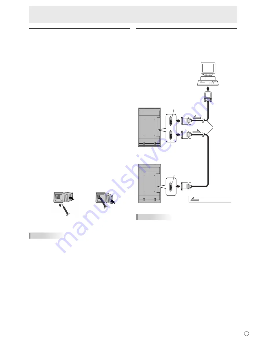
Connecting multiple monitors

You can connect multiple monitors (up to 5 monitors) in a 
daisy chain by using the PC1/AV1 input terminals and PC/AV 
output terminals of this monitor.

Connection example

Digital signal 
(DVI) cables 
(commercially 
available)

To PC 
digital RGB 
output terminal

shows the signal flow

PC/AV output terminal

PC1/AV1 input terminal

PC1/AV1 input terminal

First monitor

Second monitor

TIPS

•  The length of the signal cables or surrounding environment 

may affect the image quality.

•  The screen may not display properly when using terminals 

other than PC1/AV1 for the input mode. In this case, turn 
off the power to all the monitors connected in a daisy chain 
and then turn the power on again.

Summary of Contents for LDT651P

Page 1: ...OPERATION MANUAL ...

Page 2: ...mmunications Compliance Statement DOC This Class A digital apparatus meets all requirements of the Canadian Interference Causing Equipment Regulations C UL Bears the C UL Mark and is in compliance with Canadian Safety Regulations according to CAN CSA C22 2 No 60950 1 FCC Information 1 Use the attached specified cables with the LDT651P MV813 color monitor so as not to interfere with radio and telev...

Page 3: ...UTION The AC outlet shall be installed near the equipment and shall be easily accessible FOR CUSTOMERS IN U K IMPORTANT The wires in this mains lead are coloured in accordance with the following code GREEN AND YELLOW Earth BLUE Neutral BROWN Live As the colours of the wires in the mains lead of this apparatus may not correspond with the coloured markings identifying the terminals in your plug proc...

Page 4: ...rtify that the color monitor LDT651P MV813 is in compliance with Council Directive 2006 95 EC EN 60950 1 Council Directive 2004 108 EC EN 55022 EN 61000 3 2 EN 61000 3 3 EN 55024 Declaration of the Manufacturer Note This symbol mark is for EU countries only This symbol mark is according to the directive 2002 96 EC Article 10 Information for users and Annex IV and or to the directive 2006 66 EC Art...

Page 5: ...ar surface since they can block ventilation openings Do not place the product in an enclosed place such as a bookcase or rack unless proper ventilation is provided or the manufacturer s instructions are followed 9 Power cord protection The power cords must be routed properly to prevent people from stepping on them or objects from resting on them 10 The LCD panel used in this product is made of gla...

Page 6: ...ries only Install the batteries with due attention to the plus and minus sides of the batteries according to the instructions in the compartment Do not mix old and new batteries Do not mix batteries of different types Voltage specifications of batteries of the same shape may vary Replace an exhausted battery with a new one promptly If you will not use the remote control for a long time remove the ...

Page 7: ...not place the monitor on top of unstable objects or in unsafe places Do not allow the monitor to receive strong shocks or to strongly vibrate Causing the monitor to fall or topple over may damage it Do not use the monitor near heating equipment or in places where there is likelihood of high temperature as this may lead to generation of excessive heat and outbreak of fire The monitor cannot rotate ...

Page 8: ...ower Cord 12 Preparing the Remote Control Unit 12 Installing the batteries 12 Remote control operation range 12 Removing the Temporary Stand and the Handles 13 Basic Operation Turning Power On Off 14 Turning on the main power 14 Turning power on off 14 Disabling power on off operations 14 Basic Operation 15 Menu Items 17 Displaying the menu screen 17 Menu item details 18 Adjustments for PC screen ...

Page 9: ... the Utility Disk programme Do not reproduce it without permission For environmental protection Do not dispose of batteries in household waste Follow the disposal instructions for your area Part Names nFront view INPUT 6 1 2 3 4 5 7 1 LCD panel 2 Remote control sensor See page 12 3 Power LED See page 14 4 Power switch See page 14 5 Input switch See page 15 6 Handles See page 13 7 Temporary Stand S...

Page 10: ...PC AV audio output terminals See page 11 10 PC1 input terminal DVI D See page 10 AV1 input terminal DVI D See page 10 11 PC AV output terminal DVI D See page 11 12 External speaker terminals See page 11 13 Main power switch See page 14 14 AC input terminal See page 12 15 Vents 16 Hooks nRemote control unit 1 2 3 4 5 6 9 8 7 1 Signal transmitter 2 POWER button See page 14 3 MUTE button See page 15 ...

Page 11: ... a housing or for other reasons take other measures to keep the ambient temperature between 0 C and 40 C such as installing a fan in the housing This monitor must be installed in a vertical orientation only It cannot be installed in a horizontal orientation Do not block any ventilation openings If the temperature inside the monitor rises this could lead to a malfunction After mounting it is recomm...

Page 12: ...graphics board to verify that input signals conform to specifications of this monitor Hsync 66 3 kHz Vsync 60 Hz and Dot frequency 148 5 MHz See page 34 If there is a check box to disable EDID in display control panel check it when using PC3 BNC Use the automatic screen adjustment when a PC screen is displayed for the first time using PC2 or PC3 or when the setting of the PC is changed See page 22...

Page 13: ...C input output terminals You can control the monitor from a PC by connecting a commercially available RS 232 straight cable between this terminal and the PC See page 24 Connecting external speakers Be sure to use external speakers with an impedance of 6 Ω and a rated input of at least 7 W 1 2 1 While pushing the tab insert the tip of the cable 2 Release the tab TIPS Be sure to connect the and term...

Page 14: ... sensor 10 5 m 5 m 5 m Remote control sensor 10 TIPS Do not expose the remote control unit to shock by dropping or stepping on it This could lead to a malfunction Do not expose the remote control unit to liquids and do not place it in an area with high humidity The remote control unit may not work properly if the remote control sensor is under direct sunlight or strong lighting Objects between the...

Page 15: ...mporary use only until the monitor is properly mounted 1 Hold the monitor with the handles to prevent it from falling down and remove the stand fixing screws 4 2 Lift the monitor by holding it with the handles and the underside of the unit 3 When the installation is complete attach the included stand hole protection covers using the supplied screws 1 Remove the screws from the monitor unit 2 Secur...

Page 16: ...lternately in red and orange in standby mode Date time setting If the time has yet to be set when the monitor is first turned on the date time setting screen appears Set the date and time DATE TIME SETTING SET CANCEL 07 OK MENU 20 01 01 00 00 1 Press or to select the date and time and press or to change the numerical values 2 Select SET and then press MENU Be sure to set the date and time The date...

Page 17: ...U M E 15 Press or to adjust the volume of the sound If you do not press any buttons for about 4 seconds the VOLUME menu automatically disappears 5 BRIGHT Backlight adjustment Pressing or displays the BRIGHT menu when the menu screen is not displayed B R I G H T 15 Press or to adjust the brightness If you do not press any buttons for about 4 seconds the BRIGHT menu automatically disappears 6 SIZE S...

Page 18: ...onitor s screen size switching or dual screen display functions to compress or expand the screen for commercial or public viewing in establishments like cafes or hotels may infringe on the rights of the creators as protected by Copyright Law so please be careful When Enlarge is set the screen size is fixed to WIDE mode When dual screen display is selected the screen size cannot be changed The appe...

Page 19: ...4 kHz 4 Press or to adjust the setting AUTO CONTRAST BLACK LEVEL SHARPNESS 40 96 12 PC2 ANALOG 1 2 PICTURE SCREEN PICTURE AUDIO SETUP OPTION ENLARGE PIP PbyP OK MENU 1 0 2 4 x 7 6 8 V 60 Hz H 48 4 kHz For items that have press make settings and then press MENU 5 Press MENU twice to close the menu screen TIPS The menu will differ depending on the input mode The menu screen will close automatically ...

Page 20: ... Adjusts the entire brightness of the video signals TINT AV input Adjusts the hue Selecting changes the colour towards green and selecting changes it towards magenta COLORS AV input Adjusts the colour intensity SHARPNESS Adjusts the sharpness of the image ADVANCED AV input You can adjust more specifically See page 22 COLOR MODE Changes the colour mode on the screen The colour mode on the screen ca...

Page 21: ...ed nOPTION DATE TIME SETTING Set the date and time Press or to select the date and time and press or to change the numerical values Set the date in Year Month Day order Set the time on a 24 hour basis SCHEDULE See page 21 You can set the time to switch the monitor on and off DVI SELECT Selects equipment that is to be connected to the PC1 AV1 input terminal BNC SELECT Selects equipment that is to b...

Page 22: ...ng adjustments of ADVANCED are invalid and adjusting is disabled 3D NR MPEG NR and 3D Y C nENLARGE PC input ENLARGE MODE Sets the number of screen splits used for the enlargement See page 21 ENLARGE POS Specify the split screen to be displayed when the enlargement function is used See page 21 BEZEL H BEZEL V Sets the frame width of the display when the enlargement function is used H POS Adjust the...

Page 23: ... 3 4 5 1 Press or to select the SCHEDULE number and press 2 Set the SCHEDULE See the description below Press or to select items and press or to change the setting 3 Press MENU SCHEDULE becomes effective 1 SCHEDULE effective SCHEDULE not effective 2 POWER ON Switches the monitor on at the specified time OFF Switches the monitor off at the specified time and puts the monitor in standby mode 3 DAY OF...

Page 24: ... 4 When adjustment is finished press the Esc on the computer s keyboard to quit the adjustment programme 5 Eject the CD ROM from the CD ROM drive TIPS If the display mode on the computer you are using is 65 000 colours the colour levels in the colour pattern may appear differently or greyscale may appear to be coloured This is due to the specifications of the input signal and is not a malfunction ...

Page 25: ...n ADJUSTMENT LOCK You can disable operations on the monitor and the remote control unit that use buttons OFF Enables operation 1 Disables all operations other than turning power on off and FUNCTION 2 Only the FUNCTION operation is enabled Disables all operations other than FUNCTION not even power on off OSD DISPLAY Hides shows menus The FUNCTION screen cannot be hidden ON Displays the menus OFF Hi...

Page 26: ...put terminal RS 232C input terminal RS 232C input terminal RS 232C output terminal PC Communication conditions Set the RS 232C communication settings on the PC to match the monitor s communication settings as follows Baud rate 9600 bps Stop bit 1 bit Data length 8 bits Flow control None Parity bit None Communication procedure nCommand format When a command is sent from the PC to the monitor the mo...

Page 27: ...lowing commands is used RSET INPS ASNC WIDE EMAG EPOS PXSL POWR AGIN MWIN MWIP MWPP ESTG When control via RS 232C is locked to prevent use using the operation lock function see page 23 E C D K O L Return code 0DH 0AH nCommunication interval After OK or ERR is returned you must send the following commands To set a timeout for the command response specify 10 seconds or longer Provide an interval of ...

Page 28: ... ID number 2 VOLM0020 fl Sets volume to 20 OK 001 fl The volume of the monitor with ID number 1 the one directly connected to the PC is set to 20 The IDSL command is effective only once for the immediately succeeding command IDLK The parameter of this command sets the ID number of the monitor The monitor is subject to all subsequent commands Example IDLK0002 fl Following commands are for the monitor ...

Page 29: ... value has been returned by a specific set assign ID numbers to each monitor in advance When some monitors do not return their responses the probable cause is that the monitors could not receive the command or command processing is not complete Do not send a new command Example When 4 monitors are connected and assigned ID numbers 1 through 4 VOLM030 WAIT OK 001 OK 002 OK 003 OK 004 fl If 4 monitor...

Page 30: ...rmal mode 2 Input signal waiting mode INPUT MODE SELECTION INPS W 0 Toggle change for input mode Terminals not selected in DVI SELECT BNC SELECT cannot be selected Yes 1 PC1 DIGITAL ERR when AV DIGITAL is selected for DVI SELECT 2 PC2 ANALOG 3 AV2 COMPONENT ERR when PC ANALOG is selected for BNC SELECT 4 AV3 VIDEO 6 PC3 ANALOG ERR when AV COMPONENT is selected for BNC SELECT 7 AV1 DIGITAL ERR when...

Page 31: ... AUBS WR 10 10 10 10 BALANCE AUBL WR 10 10 10 10 RESET ARST W 3 No SETUP menu Function Command Direction Parameter Reply Control Response contents SCREEN MOTION SCSV WR 0 4 0 4 0 OFF 1 4 PATTERN 1 4 Yes MOTION TIME 1 MTIM WR 0 20 0 20 Yes MOTION TIME 2 PATTERN 1 MINT WR 10 990 10 990 Per 10 seconds Yes PATTERN 2 4 MINT WR 5 20 5 20 Per second LANGUAGE LANG WR 14 14 ENGLISH Yes 1 1 DEUTSCH 2 2 FRAN...

Page 32: ...Command Direction Parameter Reply Control Response contents ENLARGE MODE EMAG WR 0 4 0 4 0 OFF 1 2 x 2 2 3 x 3 3 4 x 4 4 5 x 5 No BEZEL WIDTH WIDTH OF THE SHORTER SIDE BEZH WR 0 100 0 100 WIDTH OF THE LONGER SIDE BEZV WR 0 100 0 100 IMAGE POSITION 2 x 2 EPOS WR 0 3 0 3 See page 21 IMAGE POSITION 3 x 3 EPOS WR 0 8 0 8 IMAGE POSITION 4 x 4 EPOS WR 0 15 0 15 IMAGE POSITION 5 x 5 EPOS WR 0 24 0 24 ENL...

Page 33: ...GHT VLMP WR 0 31 0 31 Brightness Yes TEMPERATURE SENSOR DSTA R 0 Internal temperature normal Yes 1 Internal temperature abnormal Standby mode 2 Internal temperature abnormal Temperature is normal now but it was abnormal during operation 3 Internal temperature abnormal Brightness of the backlight decreases 4 Temperature sensor abnormal TEMPERATURE ACQUISITION ERRT R Value Temperature at temperature...

Page 34: ...s connected in a daisy chain and then turn the power on again PC3 or AV2 does not appear properly Is the setting of BNC SELECT correct See page 19 Is the input signal compatible with this monitor See page 34 Control buttons do not work There is no picture Some kind of load noises from outside might interfere with normal operation Turn off the power and turn it on after waiting at least 5 seconds a...

Page 35: ... video BNC x 1 Component BNC Y Cb Pb Cr Pr 1 x 1 Audio RCA pin L R x 1 Serial RS 232C D sub 9 pin x 1 Output terminals PC AV Digital DVI D 24 pin x 1 3 Audio RCA pin L R x 1 Serial RS 232C D sub 9 pin x 1 Speaker 7 W 7 W 6 Ω Power requirement AC 100 V 240 V 50 60 Hz Operating temperature 0 C to 40 C Operating humidity 20 to 80 no condensation Power consumption 560 W Input signal waiting mode 10 W ...

Page 36: ...z 117 01 MHz 134 99 MHz 135 76 MHz Yes Yes Yes Yes Yes Yes Yes Yes Yes Yes Yes Yes Yes Yes Yes Yes Yes Yes Yes Yes Yes Yes Yes Yes Yes Yes Yes Yes Yes Yes Digital signal Yes Yes Yes Yes Yes Yes Yes Yes Yes Yes Yes Yes Yes Yes Yes Yes Yes Yes Yes Yes Yes 1 Displays a reduced image All are compliant only with non interlaced Depending on the connected PC images may not be displayed properly even if t...

Page 37: ...5 6 7 8 9 10 11 12 Function TMDS data 2 TMDS data 2 TMDS data 2 4 shield N C N C DDC clock DDC data N C TMDS data 1 TMDS data 1 TMDS data 1 3 shield N C No 13 14 15 16 17 18 19 20 21 22 23 24 Function N C 5 V GND Hot plug detection TMDS data 0 TMDS data 0 TMDS data 0 5 shield N C N C TMDS clock shield TMDS clock TMDS clock nPower management This monitor conforms to VESA DPMS and DVI DMPM Both your...

Page 38: ...36 E M E M O ...

Page 39: ......

Page 40: ... Phone 39 0 39 60531 Fax 39 0 39 6053214 E mail info projector it mee com MEU NL MitsubishiElectric Europe B V Benelux Branch http www MitsubishiElectric nl Nijverheidsweg 23a 3641 RP Mijdrecht The Netherlands Sales Phone 31 297 282461 Fax 31 297 283936 E mail info mitsubishi nl Technical Phone 31 297 282461 Fax 31 297 283936 E mail info mitsubishi nl MEU MITSUBISHI ELECTRIC EUROPE B V http www mi...

Reviews: