background image

EN-13

Viewing computer images

2

1

AUDIO OUT

AUDIO IN 1/2

2

1

2

1

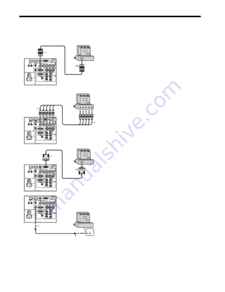
A. Connecting the projector to a computer

Preparation: 

•  Make sure that the power of the projector and that of the computer are turned off. 
•  When connecting the projector to a desktop computer, disconnect the RGB cable that is connected to the monitor. 

For analog connection: 

(For using the COMPUTER/COMPONENT VIDEO IN 2 
terminal.)

1.  Connect one end of the supplied RGB cable to the 

COMPUTER/COMPONENT VIDEO IN 2 terminal of the 
projector. 

2.  Connect the other end of the RGB cable to the monitor 

port of the computer.

•  When viewing images supplied from an analog-connected 

computer, press the COMPUTER 2 button on the remote 
control. 

For analog connection: 

(For using the COMPUTER/COMPONENT VIDEO IN 1 
terminal.)

1.  Connect one end of a commercially available BNC cable to 

the COMPUTER/COMPONENT VIDEO IN 1 terminal of the 
projector. 

2.  Connect the other end of the BNC cable to the 5 BNC 

terminals of the monitor port of the computer.

•  When viewing images supplied from an analog-connected 

computer, press the COMPUTER 1 button on the remote 
control. 

For digital connection: 

1.  Connect one end of a commercially available DVI cable 

to the COMPUTER/COMPONENT VIDEO DVI-D(HDCP) 
terminal of the projector. 

2.  Connect the other end of the DVI cable to the DVI terminal 

of the computer. 

•  When viewing images supplied from a digital-connected 

computer, press the DVI-D(HDCP) button on the remote 
control. 

•  Turn on the main power switch of the projector before 

starting the computer. 

For audio connection: 

1.  Connect one end of a commercially available PC audio 

cable to the AUDIO IN 1/2 terminal of the projector. 

2.  Connect the other end of the PC audio cable to the audio 

output terminal of the computer.

•  This projector uses stereo pin jack for its audio input. Check 

the type of the audio output terminal of the connected 
computer and prepare a proper cable for connection. Some 
computers don’t have the audio output terminal.

•  Speaker output is mono.

COMPUTER/
COMPONENT 
VIDEO IN 2

COMPUTER/
COMPONENT 
VIDEO DVI-D(HDCP)

To monitor port

RGB cable

DVI cable (option)

To DVI

Computer

PC audio cable (option)

To audio output 
terminal

2

1

R/P

R

G/Y B/P

B

H/HV

V

V

H/HV B/P

B

G/Y R/P

R

COMPUTER/
COMPONENT 
VIDEO IN 1

•  Additional devices, such as a conversion connector and an analog RGB output adapter, are required depending 

on the type of the computer to be connected.

•  Use of a long cable may decrease the quality of projected images. 
•  Images may not be projected correctly, depending on the type of the connected computer. 
•  When DVI-D signal is input, some signal setting menus are unavailable. 
•  Also read the instruction manual of the equipment to be connected. 
•  Contact your dealer for details of connection.

To monitor 
port (5 BNC)

Computer

Computer

Computer

BNC cable (option)

Summary of Contents for LC62 CHASSIS XL6500LU

Page 1: ...XL6600 XL6500 LCD PROJECTOR MODEL XL6600U XL6500U XL6600LU XL6500LU User Manual This User Manual is important to you Please read it before using your projector ...

Page 2: ... the attached specified power supply cord If you use another power supply cord it may cause interference with radio and television reception Use the attached RGB cable and RS 232C cable and the shielded LAN cable with this equipment so as to keep interference within the limit of a FCC Class B device This apparatus must be grounded DO NOT LOOK DIRECTLY INTO THE LENS WHEN THE PROJECTOR IS IN THE POWE...

Page 3: ...pose of this equipment at your local community waste collection recycling centre In the European Union there are separate collection systems for used electrical and electronic product Please help us to conserve the environment we live in Trademark Registered trademark The trademark of PJLink is trademark applied for registration or registered trademark in Japan the United States and other countrie...

Page 4: ...ids Never push objects of any kind through openings of this projector as they may touch dangerous voltage points or short out parts that could result in a fire or electric shock Never spill liquid of any kind on the projector 14 Servicing Do not attempt to service this projector by yourself Refer all servicing to qualified service personnel 15 Damage requiring service Unplug this projector from the ...

Page 5: ...etc and flammable aerosols near the projector Flammable substances may ignite causing fire or breakdown because the temperature inside the projector rises very high while the lamp is illuminating Do not use the projector with condensation on it It can lead to breakdown or other failure Place of installation For safety s sake refrain from setting the projector at any place subjected to high temperat...

Page 6: ...s according to your local regulations Batteries may explode if misused Do not recharge disassemble or dispose of them in fire Be sure to handle the batteries according to the instructions Load the batteries with its positive and negative sides correctly oriented as indicated on the remote control Keep batteries out of reach of children and pets Remove the batteries if the remote control is not used...

Page 7: ...AL terminal D SUB 9 pin 4 USB COMPUTER terminal 5 COMPUTER COMPONENT VIDEO DVI D HDCP termi nal DVI D 24 pin 6 COMPUTER COMPONENT VIDEO IN 1 terminals R PR G Y B PB H HV V BNC 7 AUDIO IN 1 terminal Mini jack The AUDIO IN 1 terminal is used for both COMPUTER 1 and DVI input 8 AUDIO IN 2 terminal Mini jack 9 Main power switch O OFF I ON 10 Power jack 11 COMPUTER COMPONENT VIDEO IN 2 terminal Mini D ...

Page 8: ...SPLIT PiP button 28 FREEZE button 29 AV MUTE button 30 Left click button The SPLIT PiP button functions as the PiP button for this projector It doesn t function as the SPLIT button Pressing the LASER button emits a laser beam Even when you keep holding down the LASER but ton it is emitted only one minute To keep emitting it longer press the LASER button again You can disable the LASER button to pr...

Page 9: ...or When operating the remote control keep the distance from the remote control to the projector via the screen within about 5 m 15 feet The operable range of the remote control however depends on the characteristics of the screen Using the wired remote control Attached remote control for this projector can be used as a wired remote control with remote control cable Wired remote control is useful f...

Page 10: ...d along the bottom of the maximum projection area Front projection Front projection ceiling mounting Depending on the installation conditions warm air that is emitted from the exhaust vents may flow into the intake vent causing the projector to display TEMPERATURE and then stop projecting images For XL6600U and XL6500U only For XL6600LU and XL6500LU see page 48 Screen size Projection distance L Len...

Page 11: ...cted images become trapezoidal If you cannot make the projector and the screen perpendicular to each other by mechanical adjustments adjust keystone To adjust keystone Press the KEYSTONE button on the projector or the remote control to display KEYSTONE and adjust the image by pressing the X W S or T button or VOLUME or button on the remote control LENS SHIFT FAST SELECT ENTER Adjustment feet Scree...

Page 12: ...n Do not install the projector near a fire alarm because it emits hot air from its exhaust vents For rear projection set IMAGE REVERSE in the IN STALLATION menu to MIRROR See page 24 Caution Placing the projector directly on a carpet impairs ventilation by the fans causing damage or failure Put a hard board under the projector to facilitate ventilation Place the projector at least 50 cm or 20 inche...

Page 13: ...o the DVI terminal of the computer When viewing images supplied from a digital connected computer press the DVI D HDCP button on the remote control Turn on the main power switch of the projector before starting the computer For audio connection 1 Connect one end of a commercially available PC audio cable to the AUDIO IN 1 2 terminal of the projector 2 Connect the other end of the PC audio cable to...

Page 14: ...tered it may cause fire or electric shock Caution Plug in the power cord firmly When unplugging hold and pull the power plug not the power cord Do not plug in or out the power cord with your hand wet It may cause electric shock Earthing terminal Power cord example About DDC The COMPUTER COMPONENT VIDEO IN 2 terminal of this projector complies with the DDC1 2B standard and the COMPUTER COMPONENT VIDE...

Page 15: ...tched from COMPUTER 1 to COMPUTER 2 to DVI at every press of the COMPUTER button on the projector The projector automatically selects the appropriate signal format The selected signal format is displayed on the screen You cannot change the input source while the menu is being displayed Though it may take some time before an image is displayed on the screen depending on the type of the input signal...

Page 16: ...tion of this product AV mute The video and audio signals are temporarily muted when the AV MUTE button is pressed To cancel muting press the AV MUTE button again It takes several seconds before muting is completely canceled If MUTE MODE in the INSTALLATION menu is set to IMAGE the splash screen will appear when the AV MUTE button is pressed You can alter the splash screen optionally See page 32 Th...

Page 17: ...nt are BNC Y C type connect Y and C to the S VIDEO IN Y and C terminals BNC type respectively Select S VIDEO as the input source When using the S VIDEO IN Y and C terminals BNC type and the S VIDEO IN terminal S type at the same time the video signal input to the S VIDEO IN terminal S type takes priority When connecting a monophonic video device use the white L terminal to connect the audio cable ...

Page 18: ...projected images Connection for video equipment having an HDMI terminal Use a commercially available DVI HDMI conversion cable Some cables may not be connected correctly depending on the size and shape of their connectors Use AUDIO IN 1 terminal for audio input Equipment having an HDMI terminal To HDMI terminal COMPUTER COMPONENT VIDEO DVI D HDCP To audio input terminals To audio output terminals ...

Page 19: ...of the connected device This depends on the black level setting of the connected device There are 2 kinds of methods to digitally transfer image data in which different black level settings are employed respectively Therefore the specifications of the signals output from DVD players differ depending on the type of the digital data transfer method they use Some DVD players are provided with a functi...

Page 20: ... is being displayed Though it may take some time before an image is displayed on the screen depending on the type of the input signal such symptom is not a malfunction Some images become easier to view when the setting of aspect ratio is changed See page 21 When projecting images from a DVD player that is connected to the COMPUTER COMPONENT VIDEO DVI D HDCP terminal press the COMPUTER button on th...

Page 21: ...cord from the outlet When you repeat turning off the main switch within 30 minutes from the lamp illumination an error may occur in the clock function of this product Volume from the speaker Press the VOLUME or button to change the volume from the speakers The volume control bar will appear on the screen VOLUME 15 The volume control bar will disappear about 10 seconds after the VOLUME button is re...

Page 22: ...0 9999 CLAMP POSITION 1 255 CLAMP WIDTH 1 63 LPF ON OFF OVER SCAN 100 90 SHUTTER L 0 20 SHUTTER U 0 20 SHUTTER RS 0 20 SHUTTER LS 0 20 VERT SYNC AUTO OFF 6 3 8 2 3 8 8 8 3 9 2 3 8 3 8 5 AUTO FILM VIDEO CINEMA MODE 3 8 2 3 8 3 8 6 6 OFF BEGIN 0 99 END 0 99 COMPUTER INPUT SYNC TYPE LAMP TIME LOW INPUT RESOLUTION HORIZONTAL FREQUENCY VERTICAL FREQUENCY AUTO RGB YCBCR YPBPR AUTO OFF 3 75 7 5 OFF 5 10 ...

Page 23: ...See page 28 ADVANCED MENU NOISE REDUCTION ON OFF Use to reduce noise and roughness in the image when noisy video signal is input CTI ON OFF Use to correct smeared color boundaries INPUT LEVEL 5 For analog signal input The input level of video signal differs among devices to be connected High input level causes solid white in displayed image and low input level causes displayed image to get dark Us...

Page 24: ...r BLACK or IMAGE which will be displayed when the AV MUTE button is pressed When IMAGE is chosen the splash screen will be displayed IMAGE REVERSE OFF Select when viewing images from the front with the projector installed on the floor MIRROR Select when viewing images projected from the behind of the screen with the projector installed on the floor INVERT Select when viewing images projected from th...

Page 25: ...ated VIDEO SIGNAL 8 options When AUTO is selected the appropriate video format is automatically selected depending on the input signal If the image isn t displayed correctly select the desired video format manually SETUP AUTO Select to change the SETUP mode automatically OFF Select to make black lighter 3 75 7 5 Select to make black thicker When 7 5 is chosen the brightness is decreased by the set...

Page 26: ...ting is automatically selected RGB Select this option when connecting the projector to high definition video equipment having R G and B output terminals YCBCR YPBPR Select this option when connecting the projector to a DVD player or other device having Y CB and CR or Y PB and PR component video output terminals OVER SCAN 100 90 Use to adjust the display area of projected image HOLD OFF ON Use to ad...

Page 27: ... yellow When it reaches 3800 hours the bar turns to red INPUT Indicates the name of the terminal to which the currently projected video signal is being input RESOLUTION Indicates the resolution of the currently projected video signal VERTICAL FREQUENCY Indicates the vertical frequency of the currently projected video signal HORIZONTAL FREQUENCY Indicates the horizontal frequency of the currently p...

Page 28: ...for menu setting 1 Display the IMAGE menu 2 Select COLOR or TINT by pressing the S or T button COLOR or TINT is unavailable when COMPUTER1 COMPUTER2 or DVI is selected as the input source TINT is available only when the NTSC signal is input 3 Adjust the selected item by pressing the W or X button To cancel the menu 4 Press the MENU button COLOR Use to adjust the color thickness of the projected im...

Page 29: ...perature Decrease the CONTRAST B blue and increase the CONTRAST R red If you set all of CONTRAST R G and B to negative values the original brightness of the image can t be obtained even when you maximize CONTRAST in the IMAGE menu CONTRAST B 0 BRIGHTNESS R 0 CONTRAST R COLOR TEMP USER 0 CONTRAST G 0 BRIGHTNESS G 0 BRIGHTNESS B 0 Color Enhancer You can set the user defined balance between the bright...

Page 30: ...setting menu of your computer Example In the case of Windows PC right click on the desktop select Properties and click the Settings tab to display the screen resolution setting The screen resolution setting of your computer is different from the setting of RESOLUTION MEMORIZE in the SIGNAL menu of the projector Select RESOLUTION MEMORIZE in the SIGNAL menu and press the ENTER button Set HORIZ PIXE...

Page 31: ... on the right or left half of the image Adjust SHUTTER LS or SHUTTER RS in the SIGNAL USER menu Noise appears on the top or bottom part of the image Adjust SHUTTER U or SHUTTER L in the SIGNAL USER menu 1 Display the SIGNALmenu 2 Press the S or T button to select an item to adjust 3 Adjust the selected item by pressing the W or X button To cancel the menu 4 Press the MENU button Do not change the ...

Page 32: ...layed make sure that the setting of SPLASH SCREEN in the INSTALLATION menu isn t OFF See page 24 To display the captured image while the video is muted set MUTE MODE in the INSTALLATION menu to IMAGE See page 24 When BACK COLOR in the INSTALLATION menu is set to IMAGE the captured image will be displayed while no signal is supplied In the mute mode or when no signal is input it takes longer time t...

Page 33: ...ENU ACCESS and SPLASH ID SCREEN When the password has already been set the mode won t be changed In such cases press the ENTER button to cancel the password func tion and try again 4 Press the ENTER button The screen for setting the password function will appear 5 Press the ENTER button The screen for entering a password will appear 6 Enter a 4 8 digit password using the S X T or W buttons on the ...

Page 34: ...P mode isn t available with some input signals For further information see page 46 When the COMPUTER 1 COMPUTER 2 or DVI D HDCP button on the remote control or the COMPUTER button on the control panel is pressed the PinP mode will be canceled The PinP mode is available only when the ASPECT ratio is set to AUTO Advanced features continued Magnifying the displayed image By pressing the MAGNIFY butto...

Page 35: ...mote control correctly To extend the cable length you are recommended to use a repeater COMPUTER VIDEO S VIDEO DVI D HDCP HOME Page Up END Page Down AUTO POSITION KEYSTONE LENS SHIFT ZOOM FOCUS 1 2 MENU ENTER LASER R CLICK USB Mouse pointer Use to move the cursor on the image instead of the computer mouse R CLICK button This operates in the same way as the right button on the computer mouse L CLIC...

Page 36: ...tware is required For the specifications of PJLink access to the Web site of Japan Business Machine and Information System Industries Association JBMIA http pjlink jbmia or jp english This projector is fully compliant to the specifications of JBMIA PJLink Class 1 It supports all the commands defined by PJLink Class 1 and the compliance has been verified with the PJLink standard specifications Version 1...

Page 37: ...n it is set to STANDARD this duration will be shorted 1 2 When LAMP MODE is set to STANDARD this duration will be shorted up to 2000 hours Lamp operation time warning Total lamp operation time reached 3000 hours 1 while the power was on Lamp operation time warning Total lamp operation time reached 3000 hours 1 while the power was off Lamp operation time warning Total lamp operation time reached 40...

Page 38: ... is now in standby This package includes a sticker which shows that the anti theft alarm device is active Visible placement of this sticker is recommended To temporarily halt the anti theft alarm device insert the safety pin Vibrations will not cause the alarm to sound for several seconds after the power switch is turned ON Vibrations will not cause the alarm to sound for several seconds after the...

Page 39: ...CHANGE will appear on the screen for 1 minute every 20 hours 1 thereafter When the lamp operation time exceeds 4000 hours 1 2 the projector automatically shuts off and can t be used until the lamp is replaced and the lamp operation time is reset 1 Duration when LAMP MODE of the INSTALLATION menu is set to LOW When it is set to STANDARD this duration will be shorted 2 When LAMP MODE is set to STAND...

Page 40: ...lips screwdriver to secure the lamp cover Reset of the lamp operation time 11 Plug the power cord into the wall outlet and turn on the main power switch 12 Hold down the W X and POWER buttons on the control panel at the same time about 3 seconds Important Unless these 3 buttons are held down at the same time the lamp operation time isn t reset Make sure that the STATUS indicator is lit twice and t...

Page 41: ...r thoroughly and let it dry completely 4 Attach the air filter to the filter cover 5 Attach the filter cover to the projector Make sure that the air filter is attached correctly without displacement Important If the filter is damaged or becomes extremely dirty change it with a new filter Contact your dealer for a new filter Use the dedicated filter only The power will not turn on if the filter cover is imp...

Page 42: ... the AV MUTE button Check that the lens cap is removed It may take about 1 minute for the lamp to light up The lamp fails to light up on rare occasions In such a case wait for a few minutes and then try again If the projector was turned off before the lamp was cooled down sufficiently last time the fan may start rotating and the POWER button may not work after the main power switch is turned on Aft...

Page 43: ...cting an evenly bright image Such image burn in phenomenon where afterimages persist on the screen may occur if a stationary image is kept displayed on the screen for a long time Red blue and green dots appear in projected images Black dots appear in projected images This phenomenon is unique to LCD projector and isn t a product malfunction A small number of pixels always stay on or off which are ...

Page 44: ...again TEMPERATURE is displayed This indication appears when the ambient temperature rises high When the ambient temperature stays high the lamp goes out J Eliminate any causes of the rise in the ambient temperature This indication appears when the air inlet or outlet grille is blocked When they are kept blocked the lamp goes out J Remove the objects blocking the air inlet or outlet grille The mark...

Page 45: ... Audio output Signal type Terminal type Line RGB Component Stereo mini jack ø3 5 1 Speaker 10 W Mono Round type ø4 5 cm x 1 Control terminal others RS 232C D SUB 9 pin USB LAN RJ 45 REMOTE IN OUT Operating temperatures 41 F 5 C to 104 F 40 C Rated voltage AC100 240 V 50 60 Hz Power consumption 4 4 A Dimensions not includeing protrusion 371 mm W x 207 mm H x 434 mm D 2 projector only 443 mm W x 207...

Page 46: ... 768 SXGA70a 1152 x 864 63 85 70 01 1024 x 768 1024 x 768 SXGA75a 1152 x 864 67 50 75 00 1024 x 768 1024 x 768 SXGA85a 1152 x 864 77 49 85 06 1024 x 768 1024 x 768 WXGA60 1280 x 768 47 78 59 87 1024 x 614 1024 x 768 2 WXGA60a 1280 x 800 49 70 59 81 1024 x 640 1024 x 768 2 WXGA60b 1360 x 768 47 71 60 02 1024 x 578 1024 x 768 WXGA60c 1366 x 768 47 50 59 75 1024 x 576 1024 x 768 WXGA 60 1440 x 900 55...

Page 47: ...our computer aren t shown on the table find the compatible resolution and frequency by changing the resolution of your computer TV60 and TV50 are equivalent to 480i and 576i respectively When these signals are supplied to the VIDEO IN or S VIDEO IN terminal the signal mode is indicated as TV60 or TV50 When they are supplied to the COMPUTER COMPONENT VIDEO IN terminals the signal mode is indicated a...

Page 48: ... Height H Shortest Wide Longest Tele Standard I Movement distance H1 inch cm inch cm inch cm inch m inch m inch cm inch cm inch cm 80 203 64 163 48 122 150 3 8 209 5 3 2 4 6 22 0 56 3 3 8 100 254 80 203 60 152 189 4 8 264 6 7 3 0 8 27 4 69 4 1 10 150 381 120 305 90 229 287 7 3 402 10 2 4 5 11 40 9 104 6 1 15 200 508 160 406 120 305 382 9 7 535 13 6 6 0 15 54 4 138 8 1 20 250 635 200 508 150 381 48...

Page 49: ...40 102 30 76 31 0 8 70 178 56 142 42 107 45 1 1 85 216 68 173 51 130 55 1 4 100 254 80 203 60 152 65 1 7 150 381 120 305 90 229 100 2 5 200 508 160 406 120 305 134 3 4 The above numbers are approximate and may be slightly different from the actual measurements Projection not recommended in size will increase distortion and reduce the resolution The adjustable angle in the keystone adjustment with ...

Page 50: ...k mee com Asia CHINA Mitsubishi Electric Air Conditioning Visual Information Systems Shanghai Ltd 26 F Oriental Center 699 Nanjing Rd W Shanghai 200041 China Sales Inquiries Phone 86 21 5211 0882 3002 Fax 86 21 5211 0576 Technical Inquiries Phone 86 21 5211 0882 3020 Fax 86 21 5211 0576 HONG KONG Mitsubishi Electric Ryoden Air Conditioning Visual Information Systems HongKong Ltd 7th Floor Manulife...

Reviews: