background image

EN-29

4. SIGNAL menu 

5. USER menu

R G B 

R G B

SIGNAL 

HORIZ. POSITION

0

VERT. POSITION

0

TRACKING

0

COMPUTER 
INPUT

AUTO

FINE SYNC.

0

USER

opt.

OK

ON

HOLD

100%

OVER SCAN

A V MEMO R Y 1 

CLAMP 
POSITION

USER 

1

CLAMP WIDTH

1

LPF

OFF

SHUTTER(U)

0

SHUTTER(L)

0

VERT. SYNC

AUTO

?

SHUTTER(LS)

0

SHUTTER(RS)

0

Menu operation (continued)

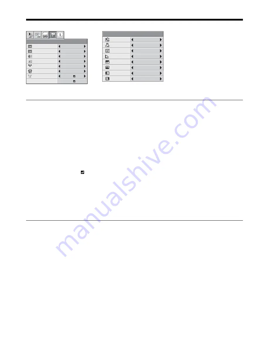
4. SIGNAL menu

ITEM

SETTING

FUNCTION

HORIZ. POSITION

0 - 999

Use to adjust the horizontal position of the projected image.

VERT. POSITION

0 - 999

Use to adjust the vertical position of the projected image.

FINE SYNC.

0 - 31

Use to eliminate fl ickering or blur, if it appears, while viewing the projected 
image. 

TRACKING

0 - 9999

Use to eliminate vertical wide stripes, if it appears, while viewing the projected 
image.

COMPUTER INPUT

AUTO

The proper setting is automatically selected.

RGB

Select this option when connecting the projector to high defi nition video 
equipment having R, G, and B output terminals.

YC

B

C

R

 / YP

B

P

R

Select this option when connecting the projector to a DVD player or other 
device having Y, C

B

, and C

R

 (or Y, P

B

, and P

R

) component video output 

terminals.

OVER SCAN

100 - 90%

Use to adjust the display area of the projected image when playing LD and 
DVD discs.

HOLD

OFF / ON 

Use to adjust the image when fl agging occurs near the top of the screen.

Though horizontal strips may appear on the enlarged projected image, such symptom is not a malfunction.
When you change the horizontal or vertical position to a large extent, noise may appear.
The adjustable range of the vertical position varies depending on the type of the input signal. Though the image 
may stay in the same position even when the setting value is changed, such symptom is not a malfunction.
If you increase the OVER SCAN setting when viewing video signals, noise may appear on the screen. In this case, 
decrease the OVER SCAN setting.

5. USER menu

ITEM

SETTING

FUNCTION

CLAMP POSITION

1 - 255

Use to correct solid white or solid black in the projected image.

CLAMP WIDTH

1 - 63

Use to correct solid black in the projected image.

VERT.SYNC

AUTO / OFF

Use to adjust the image when its motion doesn’t run smoothly. Select AUTO for 
normal use.

LPF

ON / OFF

Use to select whether or not to enable the LPF.

SHUTTER(U)

0 - 32

Use to display the black bar on the top part of the image.

SHUTTER(L)

0 - 32

Use to display the black bar on the bottom part of the image.

SHUTTER(LS)

0 - 95

Use to display the black bar on the left half of the image.

SHUTTER(RS)

0 - 95

Use to display the black bar on the right half of the image.


Summary of Contents for HC5500

Page 1: ...LCD PROJECTOR This User Manual is important to you Please read it before using your projector MODEL HC5500 User Manual HC5500 ...

Page 2: ...SILY ACCESSIBLE WARNING Use the attached specified power supply cord If you use another power supply cord it may cause interference with radio and television reception Use the attached RGB cable and RS 232C cable with this equipment so as to keep interference within the limit of a FCC Class B device This apparatus must be grounded DO NOT LOOK DIRECTLY INTO THE LENS WHEN THE PROJECTOR IS IN THE POWE...

Page 3: ...logo is a trademark of EICTA Other brand or product names are trademarks or registered trademarks of their respective holders Your MITSUBISHI ELECTRIC product is designed and manufactured with high quality materials and components which can be recycled and reused This symbol means that electrical and electronic equipment at their end of life should be disposed of separately from your household was...

Page 4: ...he type of power please consult your appliance dealer or local power company Power cord protection Power supply cords should be routed so that they are not likely to be walked on or pinched by items placed upon or against them Pay particular attention to cords at plugs convenience receptacles and points where they exit from the appliance Do not put the power cord under a carpet Overloading Do not ...

Page 5: ... lead to breakdown or other failure Place of installation For safety s sake refrain from setting the projector at any place subjected to high temperature and high humidity Please maintain an operating temperature humidity and altitude as specified below Operating temperature between 41 F 5 C and 95 F 35 C Operating humidity between 30 and 90 Never put any heat producing device under the projector s...

Page 6: ... AA batteries R6 Replace the two batteries with new ones when the remote control is slow to respond 1 2 3 Caution Use of a battery of wrong type may cause explosion Only Carbon Zinc or Alkaline Manganese Dioxide type batteries should be used Dispose of used batteries according to your local regulations Batteries may explode if misused Do not recharge disassemble or throw them in fire Be sure to han...

Page 7: ... button T button ZOOM FOCUS button VIDEO X button Important While the menu or the screen for password entry is being displayed the HDMI COMPUTER VIDEO and AUTO POSITION buttons function as the W X and S buttons respectively 1 2 3 4 5 6 7 8 9 10 11 Control area Remote control sensor Front Foot adjustment buttons Left Right Air inlet grille Terminal board Kensington Security Lock Standard connector ...

Page 8: ...e 26 Items in the menus are shown in parentheses below CONTRAST CONTRAST Adjusts the contrast of the projected image BRIGHTNESS BRIGHTNESS Adjusts the brightness of the projected image COLOR TEMP COLOR TEMP Selects one of the preset color temperatures Adjustment of USER mode is also available See page 32 GAMMA GAMMA MODE Selects one of the preset gamma mode Adjustment of USER mode is also availabl...

Page 9: ...rojector pointing the IR beam at the remote control photo sensor front or rear of the projector Keep the remote control photo sensor out of direct sunlight or fluorescent lamp light Keep the remote control photo sensor at least 2 m 6 feet away from fluorescent lamps Otherwise the remote control may malfunction If there is an inverter operated fluorescent lamp near the remote control the remote contro...

Page 10: ... To display the menu on the screen adjust SHUTTER U in the SIGNAL USER menu to position the menu Basic setup Determine the distance from the screen to the projector according to the size of the images to be projected See page 12 W A A B B Depending on the installation conditions warm air that is emitted from the exhaust vents may flow into the intake vent causing the projector to display TEMPERATUR...

Page 11: ...rpendicular to each other by mechanical adjustments adjust keystone With the INSTALLATION menu See page 26 for menu setting Display the INSTALLATION menu Select KEYSTONE by pressing the S or T button Equalize the widths at the top and bottom of the screen by pressing the W or X button viewing the screen To cancel the menu Press the MENU button several times The best adjustment result can be obtain...

Page 12: ... 4 210 5 3 34 86 200 508 120 305 160 406 90 229 160 406 15 38 232 5 9 281 7 1 45 114 250 635 150 381 200 508 113 286 200 508 19 48 291 7 4 56 143 The above figures are approximate and may be slightly different from the actual measurements Projection distance changes according to the setting of SCREEN SIZE in the ADVANCED MENU in the IMAGE menu The table above is in the case of 16 9 When the aspect ...

Page 13: ... use the projector in the following locations and manners which may cause fire or electric shock In a dusty or humid place In a sideways position or with the lens facing down Near a heater In an oily smoky or damp place such as a kitchen In direct sunlight Where the temperature rises high such as in a closed car Where the temperature is lower than 41ºF or 5ºC or higher than 95ºF or 35ºC Setting up ...

Page 14: ...ojector and the connected devices are located too close to each other the projected image may be affected by their interference See the owner s guide of each device for details about its connections Preparation Make sure that the power of the projector and that of the video equipment are turned off Basic home theater system connection Video player Set top box or digital tuner Viewing video images ...

Page 15: ...on that is a function not to display channels that are not being received enabled Connecting to a DVD player or HDTV decoder To connect this projector to video equipment that has component video output terminals such as a DVD player use the COMPONENT VIDEO IN terminals The terminal s names Y PB and PR are given as examples of when a HDTV decoder is connected The terminal s names vary depending on ...

Page 16: ...ct the image may not be projected properly Use of a long cable may decrease the quality of projected images Connection for video equipment having an HDMI terminal Use a commercially available HDMI with HDMI logo cable Some cables may not be connected correctly depending on the size and shape of their connectors Equipment having an HDMI terminal To HDMI terminal To HDMI IN 1 or HDMI IN 2 terminal T...

Page 17: ...ropriate power cord separately Use 100 240 V AC 50 60 Hz to prevent fire or electric shock Do not place any objects on the power cord or do not place the projector near heat sources to prevent damage to the power cord If the power cord should be damaged contact your dealer for replacement because it may cause fire or electric shock Do not modify or alter the power cord If the power cord is modified o...

Page 18: ... VIDEO COMPONENT HDMI1 or HDMI2 button on the remote control that is corresponding to the terminal in use The input source is switched between VIDEO S VIDEO and COMPONENT every time you press the VIDEO button on the projector The input source is switched between COMPUTER HDMI1 and HDMI2 every time you press the HDMI COMPUTER button on the projector The projector automatically selects the appropria...

Page 19: ... loud sound during cooling such symptom is not a malfunction Unplug the power cord from the outlet The POWER indicator will go out If the power cord should be unplugged accidentally while either the air inlet fan or the air outlet fans are operating or the lamp is on allow the projector to cool down for 10 minutes with the power off To light the lamp again press the POWER button If the lamp doesn ...

Page 20: ...80i 576i 480p 576p 16 9 image 720p 1080i 1080p 2 35 1 image Bold frames are recommended modes When ASPECT is set to AUTO an optimum aspect ratio is automatically selected depending on the input signal When ASPECT is set to ZOOM1 ZOOM2 or ANAMORPHIC1 display position can be changed with S or T button on the remote control OVER SCAN in the SIGNAL menu is not available in the STRETCH mode Display pat...

Page 21: ...in signals With the FEATURE menu See page 26 for menu setting Display the FEATURE menu Select ASPECT by pressing the S or T button Select your desired aspect ratio by pressing the W or X button To cancel the menu Press the MENU button Important When a 4 3 image is kept displayed for a long time before displaying 16 9 image the afterimages of the black bars may appear on the 16 9 image screen See p...

Page 22: ...h as a conversion connector and an analog RGB output adapter are required depending on the type of the computer to be connected Use of a long cable may decrease the quality of projected images Also read the instruction manual of the equipment to be connected Images may not be projected correctly depending on the type of the computer connected Contact your dealer for details of connection About DDC...

Page 23: ... input source Press the HDMI COMPUTER button on the projector or the COMPUTER button on the remote control to select COMPUTER The input source is switched between COMPUTER HDMI1 and HDMI2 every time you press the HDMI COMPUTER button on the projector Though it may take some time before an image is displayed on the screen depending on the type of the input signal such symptom is not a malfunction I...

Page 24: ...mes If it should still fail to light up replace the lamp Cover the lens with the lens cap to protect it from dust 12 13 14 15 AUTO POSITION button Viewing computer images continued POWER button OFF button AUTO POSITION button When connecting to a notebook computer When the projector is connected to a notebook computer images may not be projected in some cases In such cases set the computer so that...

Page 25: ...NU POSITION 1 Upper left 2 Lower right UNLOCK OK MENU DIMMER ON OFF CINEMA MODE 2 AUTO VIDEO FILM VIDEO SIGNAL 3 AUTO NTSC PAL SECAM 4 43NTSC PAL M PAL N PAL 60 SETUP 1 AUTO OFF 3 75 7 5 SCART INPUT 8 ON OFF LANGUAGE English Español Deutsch Français Italiano PORTUGUÊS RESET ALL OK SIGNAL HORIZ POSITION 6 0 999 4 VERT POSITION 6 0 999 4 FINE SYNC 5 6 0 31 TRACKING 1 5 6 0 9999 4 COMPUTER INPUT 5 AU...

Page 26: ... image AUTO IRIS AUTO OFF Select the operation mode of the auto iris See page 32 TRNR 0 15 Use to reduce random noise See page 33 MNR 0 15 Use to reduce mosquito noise See page 33 BAR ON OFF Use to reduce block noise See page 33 CTI 0 5 Use to correct smeared color boundaries INPUT LEVEL 5 For analog signal input The input level of video signal differs among devices to be connected High input leve...

Page 27: ...he projector installed on the floor INVERT Select when viewing images projected from the behind of the screen with the projector installed on the ceiling MIRROR INVERT Select when viewing images from the front with the projector installed on the ceiling TRIGGER OUT ON OFF Choose ON to output the trigger output signal 12 V from the TRIGGER terminal when the lamp illuminates TEST PATTERN CROSS HATCH ...

Page 28: ...g lines are remarkable select FILM when a film source signal is input or select VIDEO for other signals VIDEO The film mode will not be activated FILM Fixed to the film mode VIDEO SIGNAL 8 options When AUTO is selected the appropriate video format is automatically selected depending on the input signal If the image isn t displayed correctly select the desired video format manually SETUP AUTO Select A...

Page 29: ...d image when playing LD and DVD discs HOLD OFF ON Use to adjust the image when flagging occurs near the top of the screen Though horizontal strips may appear on the enlarged projected image such symptom is not a malfunction When you change the horizontal or vertical position to a large extent noise may appear The adjustable range of the vertical position varies depending on the type of the input si...

Page 30: ...FREQUENCY Indicates the vertical frequency of the currently projected video signal HORIZONTAL FREQUENCY Indicates the horizontal frequency of the currently projected video signal SYNC TYPE Indicates the type of the sync signal for the currently projected video signal AV memory You can store up to 3 patterns of the image quality setting for each input source To store the settings Set the items of t...

Page 31: ... image using the menu See page 26 for menu setting Display the IMAGE menu Select COLOR or TINT by pressing the S or T button Adjust the selected item by pressing the W or X button To cancel the menu Press the MENU button COLOR Use to adjust the color intensity of the projected image Every time the X button is pressed the color intensity increases Every time the W button is pressed the color intens...

Page 32: ...2 3 4 5 6 7 8 9 1 Adjusting projected images continued About color temperature There are different kinds of white color Color temperature is a way to show the differences in white White of which temperature is low appears reddish When the color temperature rises white appears bluish For example you can change the color temperature using the following procedures To rise the color temperature Increa...

Page 33: ...nd to RED GREEN and BLUE from the left respectively MID Use to adjust the gradation of the medium brightness scenes The values displayed correspond to RED GREEN and BLUE from the left respectively LOW Use to adjust the gradation of the dark scenes The values displayed correspond to RED GREEN and BLUE from the left respectively Press the W or X button to adjust the selected item Repeat steps 6 9 fo...

Page 34: ...Adjust CLAMP POSITION or CLAMP WIDTH in the SIGNAL USER menu The motion doesn t run smoothly Adjust VERT SYNC in the SIGNAL USER menu Select AUTO for normal use Noise appears on the right or left half of the image Adjust SHUTTER LS or SHUTTER RS in the SIGNAL USER menu Noise appears on the top or bottom part of the image Adjust SHUTTER U or SHUTTER L in the SIGNAL USER menu Display the SIGNAL menu...

Page 35: ...nter a 4 8 digit password using the S X T or W buttons on the remote control as shown below S 1 X 2 T 3 W 4 Press the ENTER button To cancel the procedure press the MENU button Enter the password again for confirmation using the same steps Press the ENTER button If the entered passwords don t match an error message will appear To cancel the procedure press the MENU button 1 2 3 4 5 6 7 8 9 Advanced...

Page 36: ...eplacement message LAMP EXCHANGE will appear on the screen for one minute every 25 hours 1 thereafter When the lamp operation time exceeds 5000 hours 1 2 the projector automatically shuts off and can t be used until the lamp is replaced and the lamp operation time is reset 1 Duration when LAMP MODE of the INSTALLATION menu is set to LOW When it is set to STANDARD this duration will be shorted 2 Du...

Page 37: ...oad a new lamp box securely into the projector in the right orientation Put the handle back to the original position Make sure that the handle is locked Tighten up the screws c using a Phillips screwdriver Tighten up the screw a using a Phillips screwdriver to secure the lamp cover Reset of the lamp operation time Plug in the power cord and reset the lamp operation time by holding down the W X and...

Page 38: ...ld detergent to clean the air filter Rinse the air filter thoroughly and let it dry completely Attach the air filter to the filter cover Attach the filter cover to the projector Insert the tabs on the top of the filter cover in the projector and then push the filter cover in the direction of the arrow Important If the air filter is damaged or becomes extremely dirty change it with a new air filter Contact ...

Page 39: ... panel In case of any abnormality including an abnormal rise of the inside temperature the projector may automatically turn off and go into the standby mode where the light source lamp is turned off in order to protect its internal parts Remove the accessory air filter unit from the projector Pull the accessory air filter unit in the direction of the arrow while pushing up the tabs on the bottom of ...

Page 40: ... your dealer No image appears on the screen Check that the lens cap is removed It may take about one minute for the lamp to light up The lamp fails to light up on rare occasions In such a case wait for a few minutes and then try again If the projector was turned off before the lamp was cooled down sufficiently last time the fan may start rotating and the POWER button may not work after the power co...

Page 41: ... page 31 Replace the lamp See page 36 Projected images are blurred Adjust the focus See pages 18 and 23 Clean the lens Press the W or X button on the remote control to eliminate flicker Adjust TRACKING and FINE SYNC in the SIGNAL menu See page 34 Adjust BRIGHTNESS and CONTRAST in the IMAGE menu See page 31 Adjust the projector and the screen so that they are perpendicular to each other See page 10 ...

Page 42: ...CTION in the FEATURE menu has been set to MENU ACCESS to enable the password lock Cancel the password lock or contact the person in charge of management of the projector See page 35 J Mechanical operating noise clicking sound is heard The iris produces sound while operating This is not a malfunction If the following problem occurs after the lamp is replaced check the following first Problem Solutio...

Page 43: ... warning Total lamp operation time reached 3750 hours 1 while the power was on Replace the lamp Change with a new lamp if this problem recurs Steady red Blinking red Lamp operation time warning Total lamp operation time reached 3750 hours 1 while the power was off Steady red Steady red Lamp operation time warning Total lamp operation time reached 5000 hours 1 2 while the power was off Blinking gre...

Page 44: ... 1 S video input S 1 Component video input RCA x3 YCBCR YPBPR 1 Control terminal others SERIAL RS 232C D SUB 9 pin TRIGGER DC 12 V max 200 mA stereo mini jack Operating temperatures 41 F 5 C to 95 F 35 C Rated voltage AC100 240 V 50 60 Hz Power consumption 2 5 A Dimensions 334 mm W x 125 mm H x 352 mm D Not including protrusion Weight 5 6 kg Others S video input Luminance signal Vp p 1 0 V 75 Ω ne...

Page 45: ... 37 50 50 00 1920 x 1080 2 1080p 60 1125p 60 67 50 60 00 1920 x 1080 2 1080p 50 1125p 50 56 25 50 00 1920 x 1080 2 1080p 24 1125p 24 27 00 24 00 1920 x 1080 2 PC98 640 x 400 24 82 56 42 1728 x 1080 CGA70 640 x 400 31 47 70 09 1728 x 1080 VGA60 640 x 480 31 47 59 94 1440 x 1080 2 VGA72 640 x 480 37 86 72 81 1440 x 1080 VGA75 640 x 480 37 50 75 00 1440 x 1080 VGA85 640 x 480 43 27 85 01 1440 x 1080 ...

Page 46: ...0 GND 11 GND 12 DDC Data 13 HD CS 14 VD 15 DDC Clock HDMI IN HDMI 19 pin 19 1 2 18 PIN No Spec PIN No Spec 1 TMDS Data2 11 TMDS Clock Shield 2 TMDS Data2 Shield 12 TMDS Clock 3 TMDS Data2 13 CEC 4 TMDS Data1 14 5 TMDS Data1 Shield 15 SCL 6 TMDS Data1 16 SDA 7 TMDS Data0 17 DDC Ground 8 TMDS Data0 Shield 18 5 V Power 9 TMDS Data0 19 Hot Plug Detect 10 TMDS Clock Replacement part Option not included...

Page 47: ...26 F Oriental Center 699 Nanjing Rd W Shanghai 200041 China Sales Inquiries Phone 86 21 5211 0882 3002 Fax 86 21 5211 0576 Technical Inquiries Phone 86 21 5211 0882 3020 Fax 86 21 5211 0576 HONG KONG Mitsubishi Electric Ryoden Air Conditioning Visual Information Systems HongKong Ltd 7th Floor Manulife Tower 169 Electric Road North Point Hong Kong Sales Inquiries Phone 852 2510 1505 Fax 852 2510 04...

Reviews: