(A) Application parameters
114
5.6.3
Power failure time deceleration-to-stop function
Connection and parameter setting
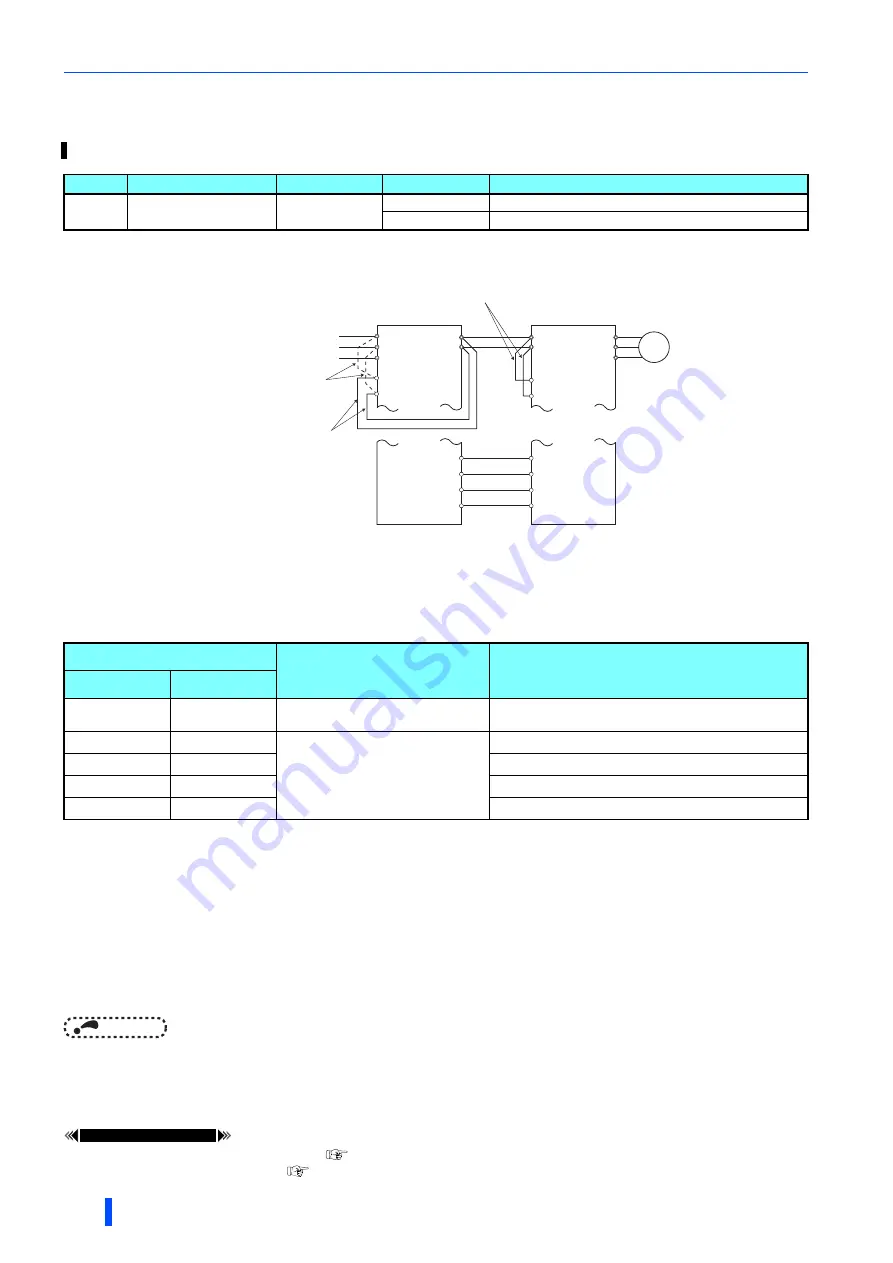
• Remove the jumpers between terminals R/L1 and R1/L11 and terminals S/L2 and S1/L21 of the converter unit, and connect
terminals R1/L11 and P and terminals S1/L21 and N. Do not remove the jumpers of terminal R1/L11 and terminal S1/L21 of
the inverter. (In the initial status of the inverter, terminals P and R1/L11 and terminals N and S1/L21 are connected.)
• Connect the terminal to which PWF signal of the converter unit is assigned and the terminal to which X48 signal of the
inverter is assigned. Also, set
Pr.261
of the converter unit in accordance with the inverter setting.
Power failure stop (PWF) signal
• Power failure stop (PWF) signal turns ON during instantaneous power failure, undervoltage, or input phase loss.
• For the PWF signal, assign the function by setting "210 (positive logic)" or "310 (negative logic)" in any of
Pr.190 to Pr.195
(Output terminal function selection)
.
When the input specification of the Power failure stop external (X48) signal is the NC contact, set the negative logic for the
PWF signal of the converter unit. When the input specification of the X48 signal is the NO contact, set the positive logic for
the PWF signal of the converter unit. (For the X48 signal, the initial setting is the NC contact input specification. For
changing the input logic, refer to the Instruction Manual of the inverter.)
NOTE
• When the power failure time deceleration-to-stop function is selected, undervoltage protection (E.UVT), instantaneous power
failure protection (E.IPF) and input phase loss protection (E.ILF) are not invalid.
• Changing the terminal assignment using
Pr.190 to Pr.195 (Output terminal function selection)
may affect the other
functions. Set parameters after confirming the function of each terminal.
Parameters referred to
Pr.190 to Pr.195 (Output terminal function selection)
Pr.872 Input phase loss protection selection
This is a function to decelerate the motor to a stop when an instantaneous power failure or undervoltage occurs.
Pr.
Name
Initial value
Setting range
Description
261
A730
Power failure stop
selection
0
0
Power failure time deceleration-to-stop function disabled
1, 2, 21, 22
Power failure time deceleration-to-stop function enabled
Pr.261 setting
Description
Power failure time deceleration-to-stop function
when the automatic restart after instantaneous
power failure is enabled (Pr.57
"9999")
Inverter
Converter unit
0
0
Power failure time deceleration-to-
stop function disabled
—
1, 11
1
Power failure time deceleration-to-
stop function enabled
Disabled
2, 12
2
Enabled
21
21
Disabled
22
22
Enabled
Power supply
Remove the jumpers.
Converter unit
Inverter
R/L1
S/L2
T/L3
R1/L11
S1/L21
U
V
W
M
R1/L11
S1/L21
P/+
N/-
P/+
N/-
Connect terminal R1/L11 and
terminal P, and connect terminal
S1/L21 and terminal N.
Keep the jumpers between terminals
R1/L11 and S1/L21 connected.
RDA
MRS(X10)
RSO
RES
PWF
X48
SE
SD
Summary of Contents for FR-CC2-P
Page 59: ...MEMO 58 ...
Page 73: ...MEMO 72 ...
Page 137: ...MEMO 136 ...
Page 153: ...MEMO 152 ...
Page 165: ...MEMO 164 ...
Page 169: ...MEMO 168 ...


