HPP Mode 4
4-1
4.
HPP Mode
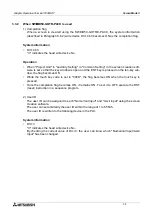
In the HPP mode, devices can be monitored, and set values and current values can be
changed from the GOT to the connected PLC.
4.1
Outline of HPP mode
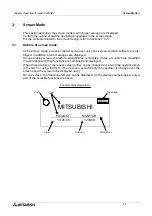
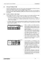
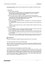
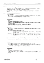
This paragraph describes the operating procedure to change over to the HPP mode and each
function available in the HPP mode.
u
u
u
u
Basic operation
•
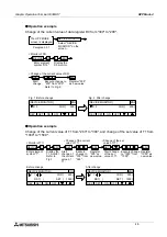
In the case of computer link connection, monitoring and the set value change range are
restricted. For the details, refer to Section 1.
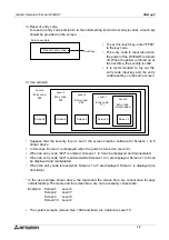
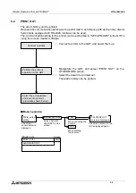
The SELECT MODE
screen is displayed.
HPP MODE
The HPP MODE
screen is displayed.
Paragraph 2.3
Select "HPP
MODE" on
the screen.
The screen shown
below is displayed.
END
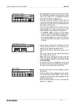
[HPP MODE]
[HPP MODE MENU]
DEVICE MONITOR
ACTIVE STATE MONITOR
PC DIAGNOSIS
1)
3)
2)
•
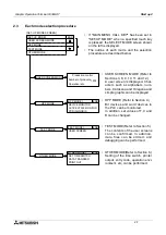
Among the following functions, 2) and 3) are valid
only when the FX Series PLC is connected.
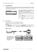
1) DEVICE MONITOR (Paragraph 4.2)
The ON/OFF status and the set value/current
value of arbitrary devices in the PLC can be
monitored. In addition, the ON/OFF status can
be forcedly set to ON/OFF and the set values/
current values can be changed.
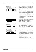
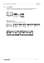
2) ACTIVE STATE MONITOR (Paragraph 4.3)
The state (S) Nos. in the ON status in the FX
Series PLC are displayed.
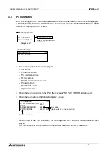
3) PC DIAGNOSIS (Paragraph 4.4)
The error information of the FX Series PLC is
displayed.
Graphic Operation Terminal F930GOT
Summary of Contents for F930GOT-BWD-E
Page 1: ...USER S MANUAL F930GOT BWD E ...
Page 4: ...Graphic Operation Terminal F930GOT ii ...
Page 6: ...Graphic Operation Terminal F930GOT iv ...
Page 14: ...vi ...
Page 60: ...Graphic Operation Terminal F930GOT Start up 2 2 10 MEMO ...
Page 68: ...Graphic Operation Terminal F930GOT Screen Mode 3 3 8 MEMO ...
Page 120: ...Graphic Operation Terminal F930GOT Creation of Display Screens 8 8 30 ...
Page 200: ...Graphic Operation Terminal F930GOT Changeover of Display Screen FX PCS DU WIN E 10 10 18 ...
Page 272: ...Graphic Operation Terminal F930GOT Additional Functions in V 2 00 or later 13 13 24 MEMO ...

