GCH15010
66
PHOTOS
DISASSEMBLY PROCEDURE
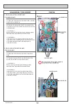
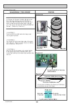
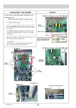
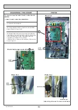
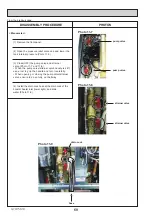
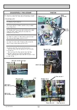
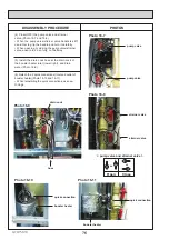
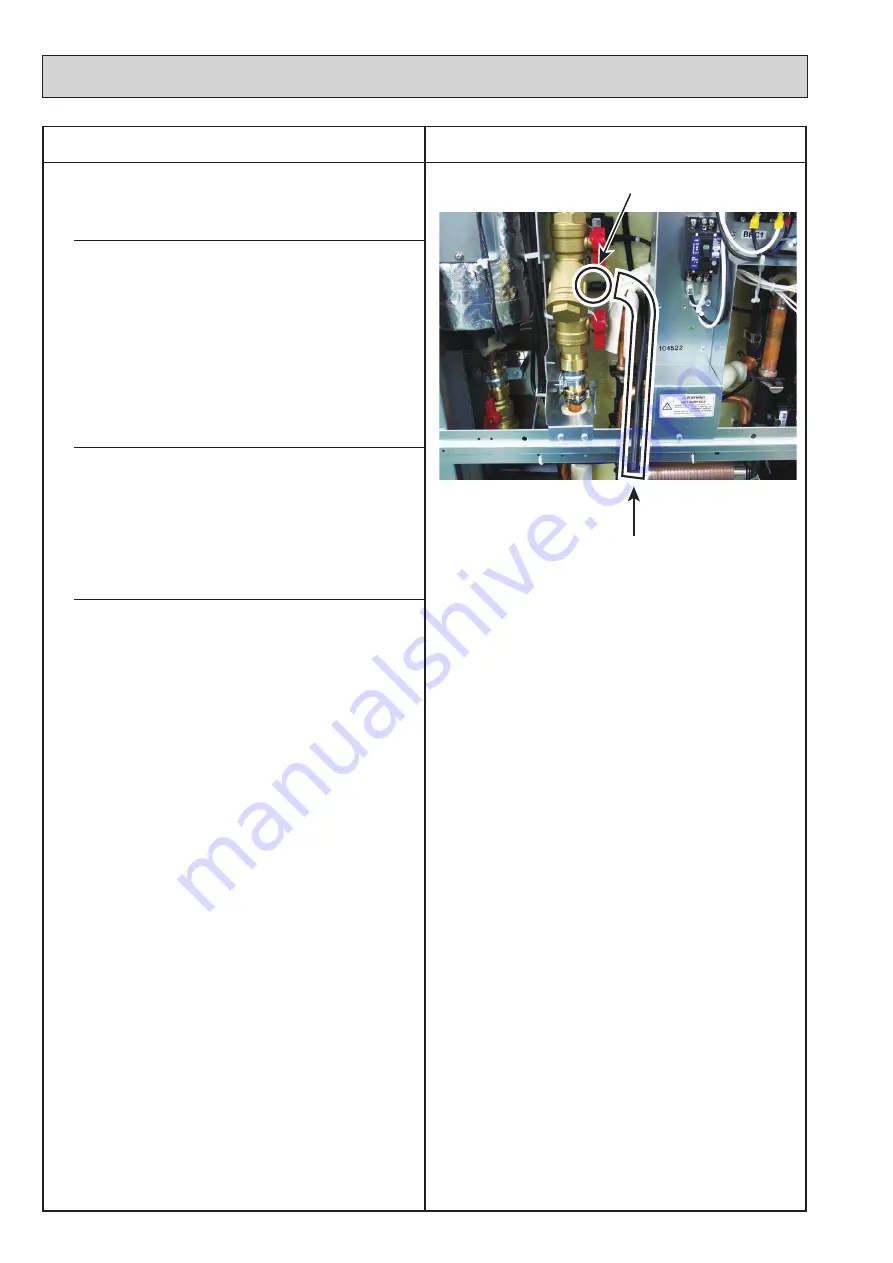
Photo 10-9
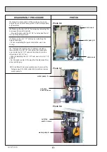
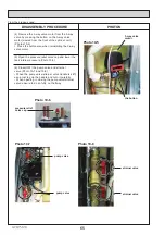
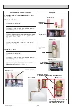
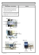
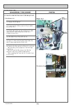
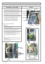
(9) Remove the 3-way valve by removing the 3 G1"
nuts in the order of the bottom, left and right using two
spanners: one to hold the 3-way valve and the other to
turn each nut.
:KHQUHLQVWDOOLQJWKH*QXWVXVHQHZ*JDVNHWV
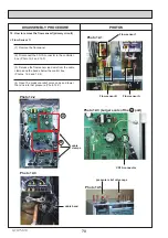
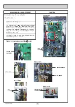
A and B shown represent the right and the left direc-
tions of the 3-way valve, respectively.
Note:
Before replacing the motor, be sure to power off the
cylinder unit.
)DLOXUHWRGRVRPD\FDXVHHOHFWULFVKRFNRUFDXVHWKH
3-way valve to malfution.
Note:
:KHQLQVWDOOLQJWKHZD\YDOYHFKHFNDJDLQWKDWWKH
TXLFNFRQQHFWLRQDUHLQVWDOOHG
:KHQUHSODFLQJWKHZD\YDOYHWDNHFDUHQRWWR
become injured by touching the left side edge of the
controller box.
From the previous page.
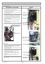
(7)
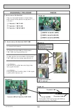
,QVWDOOWKHGUDLQFRFNKRVHDWWKHGUDLQFRFNRI
the booster heater inlet (lower right), and drain
water. (photo 10-9)
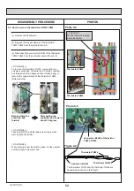
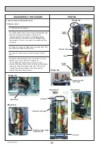
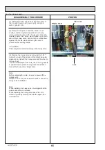
(8)
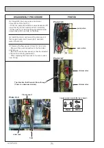
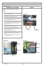
5HPRYHWKHTXLFNFRQQHFWLRQRIWKHQXWV
(bottom, left and right) connected to the 3-way
valve, and drain water in the 3-way valve from the
booster heater inlet. Since water builds up on the A
side of the 3-way valve, hold a cloth or similar item
against the A side when removing the nuts to
prevent water spilling inside.
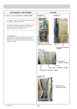
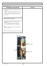
hose
drain cock
< CAUTION >
There may be hot water remaining in the 3-way valve.

