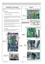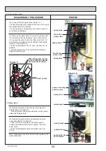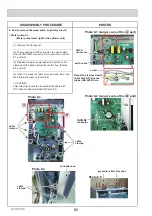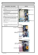
GCH15010
48
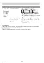
Part Name
Check Points
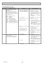
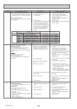
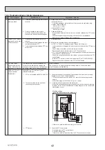
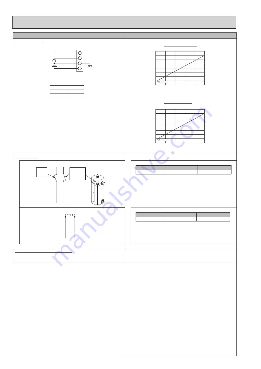
Flow sensor (1,A,B)
Flow sensor 1 , B
Flow sensor A
Booster heater
Measure the resistance between the terminals with a tester.
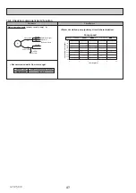
Thermostat (90 °C) and thermal cut out (121 °C)
90 °C
Manual reset
water
thermostat
121 °C
Thermal
cut-out
AWG18
AWG18
9
10
Terminal
Normal
Abnormal
9-10
80
Pȍ
Open or Short
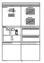
2kW heater (230V, 1 phase)
1
2
2kW
AWG15 FEP
WHITE
AWG15 FEP
WHITE
Terminal
Normal
Abnormal
1-2
ȍ
Open or Short
Earth leakage circuit breaker for heater
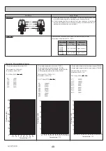
Yellow
White
Green
Brown
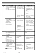
Flow signal
part name
symbol
Flow sensor 1
CN1A
Flow sensor A
CN2A
Flow sensor B
CN2B
V
5V DC
CN1A
1
4
Flow signal
4.0
3.5
3.0
2.5
2.0
1.5
1.0
0.5
0.0
0
4
8
12
16
20
0
8
16
24
32
40
Flow [l/min]
Flow output signal[V]
0.35V
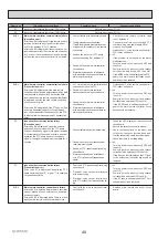
Flow signal
4.0
3.5
3.0
2.5
2.0
1.5
1.0
0.5
0.0
Flow [l/min]
Flow output signal[V]
0.35V
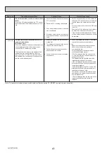
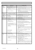
If a short circuit occurs on the booster heater, or each power line,
a short-circuit breaker will trip and power source will be blocked.
Eliminate the causes of short circuit and then turn on the breaker again.

