


70
••••••••••••••••••••••••••••••••••••••••••••••••••••••••••••••••••••••••••••••••••••••••••••••••••••••••••••••••••••••••••••••••••••••••••••••••••••••••••
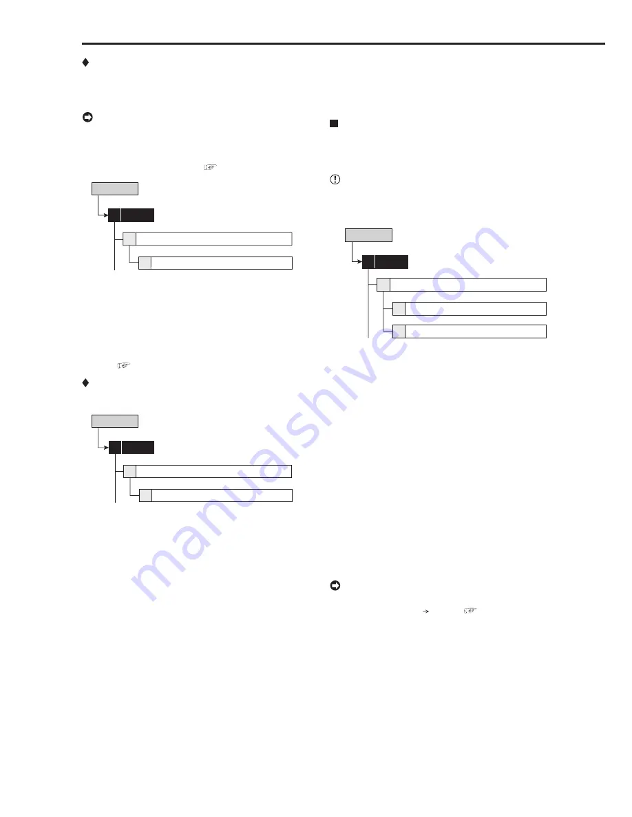
Recorder Title
This item is used to set the recorder title. When using the
cascade function, setting the name of the slave recorder to
the recorder title makes distinction of the recorder easy.
• The recorder title is displayed on the upper part of
the operational mode display.
• The recorder title can be input via a personal computer
by using the Web function. (
See page 107.)
Setup Menu
Recorder Title
4
6
On Screen Display Setting
System
4
step
1.
Set the display mode of the recorder title.
On
: Displays recorder title.
Off
: Does not display the recorder title.
step
2.
Input the recorder title by using the characters shown
on the bottom of the screen.
• When “ALERT” appears on the screen, press
HELP button to display the detailed information.
See page 114 for countermeasures.
Monitor Output Adjust
This item is used to adjust the monitor output.
Setup Menu
Monitor Output Adjust
5
6
On Screen Display Setting
System
4
step
1.
Adjust the monitor scan mode.
•
Adjust the display range of the monitor. Set it
depending on the displaying area of the monitor.
Overscan
: Displays overscaned picture. Generally,
this setting is suitable for the monitor of which
display range is narrow such as a television for
domestic use.
Underscan
: Displays underscaned picture.
Generally, this setting is suitable for the monitor of
which display range is wide such as a liquid crystal
television. The black line may appear on the right
or left side of the picture for each camera.
step
2.
Adjust the alpha blend level.
•
The picture supplied from the camera can be
viewed through the menu screen being displayed.
2-1
Menu
•
Adjust the see-through level of the menu display.
The degree of transparency becomes lower as
the higher numbered level is set.
System (continued)
Setup Menu
2-2
On Screen Information
•
Adjust the see-through level of the information
such as the clock or title.The degree of
transparency becomes lower as the higher
numbered level is set.
Audio Setting
This item is used to set the audio output for connected
cameras. This setting can be made individually for the sin-
gle screen display and the split screen display.
• Audio setting is available only when the optional audio
interface board DX-SC5 is attached to this unit.
Setup Menu
Audio Setting
7
System
4
Multiplex Display
2
Single Display
1
step
1.
Select the desired audio output for each camera
number and split screen.
• This setting is valid for the audio output during
playback or displaying a picture from a camera.
Channel 1
: When displaying the picture from a
camera, outputs audio from the AUDIO IN 1
terminal. During playback, outputs the audio
recorded from the AUDIO IN 1 terminal.
Channel 2
: When displaying the picture from a
camera, outputs audio from the AUDIO IN 2
terminal. During playback, outputs the audio
recorded from the AUDIO IN 2 terminal.
Channel 3
: When displaying the picture from a
camera, outputs audio from the AUDIO IN 3
terminal. During playback, outputs the audio
recorded from the AUDIO IN 3 terminal.
Channel 4
: When displaying the picture from a
camera, outputs audio from the AUDIO IN 4
terminal. During playback, outputs the audio
recorded from the AUDIO IN 4 terminal.
Off
: Does not output audio.
• The audio can be switched temporarily by using
<Audio> (User Menu Audio). (
See page 48.)


