background image

33

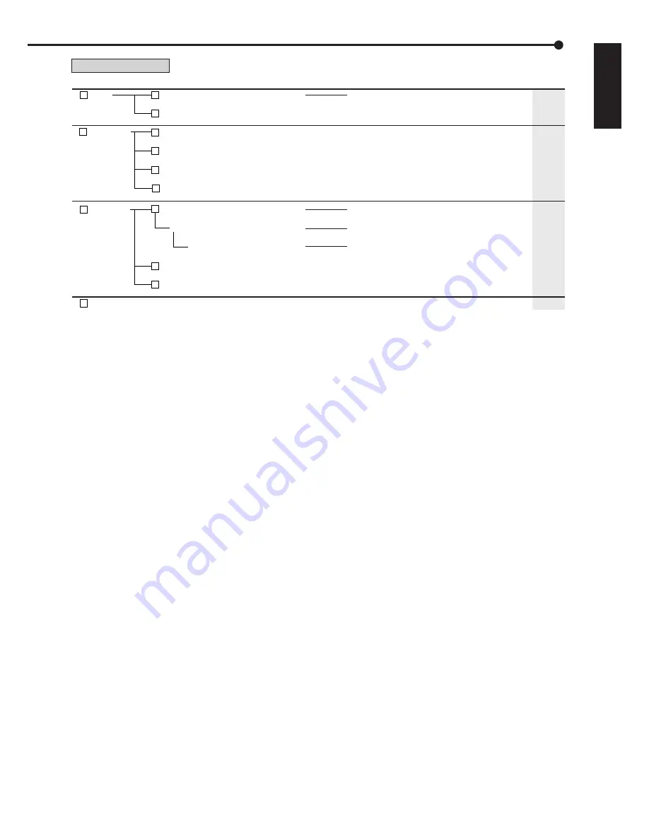
•••••••••••••••••••••••••••••••••••••••••••••••••••••••••••••••••••••••••••••••••••••••••••••••••••••••••••••••••••••••••••••••••••••••••••• Menu chart

ENGLISH

Exits the User Menu.

4

 Audio

5

 Protect Data

E

 Exit

1

 Multiplexer Setting


E

Exit

1

 Protect Recorded Data

151 000 000


2

 Protected Data Information

152 000 000


3

 Change Protected Data Settings

153 000 000


E

  Exit

Protects the recorded pictures.  Up to 500 areas 
can be protected and cannot be overwritten.
Shows and searches the list of protected 
pictures.
Shows and deletes the list of protected 
pictures.
Exits the Protect Data menu.

Switches the audio output among 1 to 4 during 
playback or displaying the picture from the camera.
Exits the Audio menu.

6

 PTZ Control

1

 Go to PTZ Control

Zoom, iris, focus adjustment, Autopan

Add Preset

2

 Select PTZ Camera

162 000 000

E

  Exit

Activates pan or tilt of the PTZ camera 
connected.
Adjusts the zoom, iris, and focus of the 
camera. Activates auto pan.
Presets up to 16 viewing positions.

Switches the PTZ camera to be controlled.

Exits the PTZ Control menu.

48

49

49

49

50

50

50

50

User Menu (100 000 000)

Menu

Menu Address

Functions

Pages

Summary of Contents for DX-TL5000E

Page 1: ...1 ENGLISH DIGITAL RECORDER INSTALLER S MANUAL MODEL DX TL5000E THIS INSTRUCTION MANUAL IS IMPORTANT TO YOU PLEASE READ IT BEFORE USING YOUR DIGITAL RECORDER ...

Page 2: ...anish Italian and Russian Function keys on the front panel or USB mouse can operate the menu on the DX TL5000E Recording rate up to 200 pps system Because of the new recording circuit and compression chip the maximum recording speed is 200 pps in total this means that the system can record pictures with speed of up to 12 5 pps on all 16 channels With this speed recorded pictures are seen by the ey...

Page 3: ...Microsoft is either registered trademarks or trademarks of Microsoft Corporation in the United States and or other countries All other company and product names appearing herein are the property of their respective owners ...

Page 4: ...cleaners Clean with a soft cloth moistened with soap and water and wipe dry PVC cables or leads should not be left in contact with the cabinet surface for long periods INSTALLATION LOCATION For excellent performance and lasting reliability install in a location that is 1 Well ventilated out of direct sunlight and away from direct heat 2 A solid vibration free surface 3 Free from high humidity exce...

Page 5: ...ck The wire which is coloured brown must be connected to the terminal which is marked with the letter L or coloured red The user will not be indemnified for problems e g recording failure or playback failure that occur with either the unit or a connected device during operation It is recommended that backups of important recordings are made regularly as a pre caution against possible breakdowns an...

Page 6: ...D DISC Do not use the disc cracked deformed or repaired with adhesive The disc may fly into pieces and cause injury Do not touch the playback surface when holding the disc When dew condensation occurs on the disc wipe the surface off before use Dirt such as fingerprints or dust causes the deterioration of the picture quality and audio quality Gently wipe the DVD CD disc from the centre to the outs...

Page 7: ...is applied In addition this Product contains Apache and OpenSSL including Original SSLeay library These software programs are also excluded from Licensed Software and not covered by the following Software License Agreement For the terms and conditions for use of these software programs please see Notice about Apache software and Notice about OpenSSL software Each of Berkeley Database agetty expat ...

Page 8: ...Information 48 Audio 48 Protect Data 49 Protect Data 49 PTZ Control 50 PTZ control using the menu 50 PTZ control using the front panel buttons 50 Setup Menu Recording 51 55 Settings concerning normal recording and alarm recording 51 Pre alarm recording 51 Set Recording Pattern A Normal Timer to D Timer 51 53 Alarm Input 53 Emergency Recording Setup 54 55 Emergency recording 54 Long pre alarm recor...

Page 9: ...ion example 2 91 Operation example 3 92 93 Operation example 4 94 95 Basic operations 96 100 Basic multiplexer functions 96 Multiplexer buttons 96 Basic manual recording 97 Setting the recording rate and picture grade for normal recording 97 Basic playback 98 Basic search 99 100 Search by Time and Date 99 Search by Alarm List 100 Viewing displays Refer to this information when operating Reference ...

Page 10: ...xer Setting on pages 66 68 Making the sequence setting See Multiplexer Setting on pages 66 68 Setting other various functions Setting the camera title recorder title See Camera Title and Recorder Title on page 69 70 Setting the display mode See On Screen Information on page 69 Setting the output signal of the unit status See Mode Out Settings on pages 60 and 61 Flowchart Flowchart for connection a...

Page 11: ...ng time Setting the PTZ camera preset See Set Recording Pattern A Normal Timer to D Timer on pages 51 53 Setting the timer program Setting the holiday Selecting the timer program number Making the timer recording settings Selecting the day of the week Selecting the start time Selecting the end time Selecting the program mode Selecting the motion detection mode Selecting the special day of the week...

Page 12: ...imple lock or password lock is turned on 8 M DET indicator Illuminates when the motion detection function is activated Flashes during motion detection recording 9 PRE ALARM indicator Illuminates during pre alarm recording It also illuminates when pre alarm recording is set 10 COPY 1 indicator Illuminates while performing copy 1 operation Flashes when starting or ending the copy 1 opera tion 11 COP...

Page 13: ...esent time and the status of the unit 19 SHUTTLE ring Adjusts the playback speed and rewinds or forwards the recorded pictures Pans the camera 20 JOG dial Forwards or rewinds the picture during playback frame by frame Uses for controlling PTZ cameras connected 21 Camera number buttons 1 to 16 Displays the picture supplied from the camera con nected The number of the button corresponds to that of t...

Page 14: ...Password Setting 30 TRIPLEX PB button In split screen display inserts the playback picture of needed camera while also displaying the live pic ture from other camera 31 BOOK MARK button When pressing this button during frame still play back of the single screen display the selection screen appears and you can memorize the book mark or copy the picture being displayed 32 DIGITAL ZOOM button Pressin...

Page 15: ...cially available antitheft cable manufactured by Kensington 10 OPTION SLOT Used to attach an optional boards 11 GND terminals Used as common GND terminal 12 RS 232C connector Used to connect to a host device equipped with RS 232C connector such as a personal computer This unit can be controlled from other devices via this connector 1 MAIN switch This is the main power switch To use this unit set t...

Page 16: ...to the CLOCK ADJ terminal For example if the current time is 11 29 59 it will be reset to 11 00 00 and if the current time is 11 30 00 it will be reset to 12 00 00 CLOCK ADJ OUT terminal Output terminal to send the signal to the other recorders connected for adjusting the clock to the nearest hour 00 minutes 00 seconds REC terminal Input terminal to start recording This terminal is not available d...

Page 17: ...DEO IN connector To OUTPUT B connector To CAMERA IN 1 connector Up to 16 cameras To GND terminal To ALARM IN terminal corresponding to the CAMERA VIDEO MONITOR SENSOR 1 POWER CORD for U K for the Continent VIDEO MONITOR To CAMERA IN connector DOME CAMERA CAMERA 1 COAX type dome camera To LAN A Clamp the USB cable using the supplied cable clamping band in order to prevent the accidental removal of ...

Page 18: ...ording connection The diagram below shows an example connection for setting alarm signal to sensor number 1 ALARM SWITCH RS 232C GND ALARM OUT 1 2 3 4 5 6 7 8 9 10 11 12 13 14 15 16 ALARM IN 1 2 3 4 5 6 7 8 9 10 11 12 13 14 15 16 Interface circuit inside the unit 5V 5V 10kΩ 22kΩ Input terminal 0 047µF GND EMERGENCY ALARM IN REC CLOCK ADJ Input terminal Input Circuit 4 7kΩ Interface circuit inside ...

Page 19: ... 7 8 9 10 11 12 13 14 15 16 RS 232C RS485 RS485 IN OUT MAIN OFF ON RESET OPTION SLOT LAN A LAN B STORAGE COM SERIAL BUS SERIAL BUS 1 2 3 4 5 6 7 8 9 10 11 12 13 14 15 16 OUT IN CAMERA OUT IN Y C OUTPUT B CLAMPER CLAMPER OUTPUT A VIDEO VIDEO VIDEO CASCADE IN OUT 10 100 10 100 100 240V AC IN MAX 350mA DC 12V OUT CLOCK ADJ CLOCK ADJ OUT REC REC STOP EMERGENCY RESERVED MODE OUT 1 MODE OUT 1 MODE OUT 2...

Page 20: ...t up the unit normally with the HDD that was being used at the time of the power failure attached Then add replace or transport the HDD HDD is very delicate Handle the HDD with care and follow the precautions below because even a small shock may damage the internal components of the HDD Do not place the HDD on a desk or a table directly Put a thick cushion under the HDD because even a small shock ...

Page 21: ...3 Remove the front covers Remove the cover on the right side first Then push the left side cover to the right to remove step4 Remove the metal part Remove 4 screws on the metal part step5 Pull out the HDD tray halfway HDD A HDD B HDD C step6 Disconnect the cables step7 Remove the HDD tray Pull out the HDD tray completely step8 Remove the HDD Remove 4 screws which are used to fix the HDD and its fr...

Page 22: ...e supplied screws step2 Insert the hard disk tray halfway step3 Connect the cords step4 Insert the hard disk tray completely step5 Attach the metal part Adjust the upper side first then push the lower side into the unit Take care not to deform the springs Spring step6 Fix the metal part with four screws step7 Attach the front covers Attach the left side cover and push to the left Then attach the r...

Page 23: ...GLISH Connections step8 Fix the front covers with two screws step9 Close the left end of each screw covers on both sides of the cover Follow the same procedures when removing or attaching the HDD B or HDD C ...

Page 24: ...tep2 Put the cable to be clamped through the cable clamping band as illustrated below Face the serrated surface of the band inside step3 Pull the edge of the cable clamping band until it stops Connecting to an analogue video cassette recorder To VIDEO OUT connector To VIDEO IN connector Analogue video cassette recorder Commercially available video cable Connections continued ...

Page 25: ... set using wired remote controller Consult your dealer for the functions related to PTZ Rack mount adapter for digital recorder DX TL5000 series step1 Remove the 13 screws on both sides 4 X 2 and rear side 5 front rear step2 Remove the top cover by pulling it to the rear panel step3 Attach the optional board When attaching the optional board follow the instruction on the manual of the optional boa...

Page 26: ...tach the supplied ferrite core to the cable of the mouse as illustrated to the left Setting a menu with a mouse step1 Use the left and right mouse buttons to set the menu Click the left button to open the menu or select a needed item etc Click the right button to select the active area for motion detection function See pages 58 and 59 The wheel on a mouse does not work with this unit Setting the m...

Page 27: ... button of the needed item or left click on the needed item The item menu opens Select an item and press the number or click on the menu to open the item 100 000 000 1 Search 4 Audio 2 Copy 5 Protect Data 3 Information 6 PTZ Control D Next E Exit User Menu Setup Menu 1 Recording System 4 2 Timer Motion Det Menu Data 5 3 Option 6 D Next E Exit 200 000 000 M DET DOT ON OFF M DET Setup Menu 1 Recordi...

Page 28: ...ft click on the parameter box until the item to be set appears step2 For some items more detailed setting is required In this case an item such as D Set is displayed If necessary press the D button or left click on the Set to set more details When you close the menu press the E button or left click on Return or Exit You cannot close the menu by pressing the SET UP button on the unit Time Date Sett...

Page 29: ...en you press the 15 button or click this symbol the value of selected item decreases Menu address A unique number for each menu page You can go directly to each menu page by inputting the menu address number using the front buttons of the unit For example when opening the Motion Search menu press the SET UP button and then press the camera number button in the order of 1 6 Motion Search Main Norma...

Page 30: ... is displayed on the LCD display on the front panel step2 Select whether or not to use the setup wizard Select Go when you want to use the setup wizard If not select Quit When selecting Quit the clock starts running from the initial setting Beware that the menu screen cannot be exited while setting the setup wizard Furthermore some menu screens which have already been set will not be displayed aga...

Page 31: ...rding settings The power of the unit turns on In the recording setting screens you can return to the previous screen by pressing the Return button step8 When selecting Next By selecting Execute the unit automatically checks the condition of the picture supplied from the camera and then sets the camera number to be recorded Select Next when the setting is completed step9 Set the recording time Set ...

Page 32: ... used to record for the specified time period Searches the desired picture by specifying a bookmark registered Searches camera picture with motions by using motion detection function during playback Sets the condition for motion detection Sets the motion detection area manually Exits the Search menu Copies the data to copy 1 device by specifying the start and end points of the data for short perio...

Page 33: ...e list of protected pictures Exits the Protect Data menu Switches the audio output among 1 to 4 during playback or displaying the picture from the camera Exits the Audio menu 6 PTZ Control 1 Go to PTZ Control Zoom iris focus adjustment Autopan Add Preset 2 Select PTZ Camera 162 000 000 E Exit Activates pan or tilt of the PTZ camera connected Adjusts the zoom iris and focus of the camera Activates ...

Page 34: ...ays the preview of the alarm recording settings Specifies the sensor settings for alarm recording Displays the recording camera for each sensor Displays the recording camera for each sensor Specifies the trigger and PTZ camera preset settings for alarm recording Displays the preview of the trigger and PTZ camera preset settings for alarm recording Specifies the recording setting for recording patt...

Page 35: ... and picture grade of alarm recording for each camera number individually Displays the preview of the alarm recording settings Specifies the sensor settings for alarm recording Displays the recording camera for each sensor Displays the recording camera for each sensor Specifies the trigger and PTZ camera preset settings for alarm recording Displays the preview of the trigger and PTZ camera preset ...

Page 36: ...overview of Program 2 Specifies the settings of Program 1 Specifies the settings of Program 2 Specifies the holidays Exits the Timer menu Adjusts time date setting and selects daylight saving setting Specifies the time period for daylight saving settings Selects menu language to be displayed Specifies the settings for MODE OUT terminal CALL OUT terminal key sound and buzzer Specifies mode out sett...

Page 37: ...lit 9b display settings Specifies the output A split 10 display settings Specifies the output A split 10a display settings Specifies the output A split 10b display settings Specifies the output A split 13 display settings Specifies the output A split 13a display settings Specifies the output A split 13b display settings Specifies the output A split 16 display settings Specifies the output A single...

Page 38: ...amera titles Specifies the recorder title Specifies the monitor output settings Specifies audio output settings Specifies audio output settings for single screen display Specifies audio output settings for split screen display Resets the menu settings to the factory settings Exits the System menu 5 Menu Data 1 Load Menu Data D Execute 251 000 000 1 Select 251 100 000 2 Save Menu Data D Execute 252...

Page 39: ...ice port settings Shows e mail addresses of alarm notification Shows the detailed alarm notification settings Shows the alarm notification settings Shows the detailed alarm notification settings Specifies LAN A settings Specifies the detailed settings for LAN A Selects NAS device to be set Displays the information of NAS device 1 Displays the information of NAS device 2 Displays the information of...

Page 40: ...lays the detailed information of the NAS group of the Copy 1 device Displays the recorded range of the SCSI group of the Copy 1 device Displays the detailed information of the SCSI group of the Copy 1 device Displays the recorded range of the DVD CD group of the Copy 1 device Displays the detailed information of the DVD CD group of the Copy 1 device Displays the recorded range of the USBmemory Dis...

Page 41: ...he main or copy device Registers or removes the internal HDD for main or copy 2 device Registers or removes the USB device for main or copy device Registers or removes the SCSI device for main or copy device Registers or removes the NAS device for the copy device Registers or removes the DVD CD drive for copy 1 or 2 device Specifies the repeat recording Specifies the partition setting of the Main ...

Page 42: ...ain Memory Change Partition Setting is set to other than 0 LPA appears when Long Pre Alarm Area System Menu Memory Data Management Setting for Main Memory Change Partition Setting is set to other than 0 When ejecting the disk make sure to use the Media Eject on the menu screen Search by Time and Date see page 99 Search by Alarm List see page 100 Find data storage location This item is used to disp...

Page 43: ...t to the earlier time than the recording start point the search is executed from the oldest recording point step3 Set the motion detection conditions for playback Set motion mask setting sensitivity and motion threshold See pages 58 and 59 for the details of these settings The sensitivity of motion detection conditions for playback has two setting items Low and High The motion detection settings f...

Page 44: ...peration during clearing the data of the DVD When copying the data while Copy Data is set to Alarm the unit performs copy operation however the data is not recorded if there is no alarm recording data within the specified range of copy In case of CD DVD disc the remaining capacity becomes low because only the management information is recorded It is recommended to carry out Calculate in Copy Data ...

Page 45: ...ecomes low because only the management information is recorded Do not use the disk which has been used on the personal computer failed to be copied or stopped during copying due to the power failure because they may cause malfunction of the unit step3 Set the start time of copy Start Sets the start point of copy Continue Starts copying from the end point of the previous copy To set the start point...

Page 46: ...he speed changes from X1 to X2 X4 X8 and back to X1 at every press of this button during reverse playback Reverse Playback Click to playback the picture in the reverse direction Field Reverse Click to display a still picture one field before Stop Click to stop playback Audio if recorded will be played back after the stop when the audio command has been enabled Field Advance Click to display a stil...

Page 47: ...en A and B Put a check mark to repeat playback between Point A and Point B you specified View menu Command Function Picture Size When clicking the options of 100 75 50 and 25 appear Pictures are zoomed in or out according to the selected magnification Decode Level When clicking the options of Fine Middle and Rough appear When setting the decode level to rough the picture becomes rough and the play...

Page 48: ...nit User Menu Multiplexer Setting Audio 4 1 step1 Select the desired audio channel CH1 Outputs the audio from the AUDIO IN 1 terminal while displaying the picture from the camera Outputs the recorded audio of AUDIO IN 1 terminal during playback CH2 Outputs the audio from the AUDIO IN 2 terminal while displaying the picture from the camera Outputs the recorded audio of AUDIO IN 2 terminal during pl...

Page 49: ...ed Data Information Select the area to be displayed in the Select Source Device User Menu Search Search Displays the picture of the start point of the selected area Check Checks the device in which the locked area is recorded step4 To cancel the lock select Disable of the desired area in the screen of Change Protected Data Settings Search Displays the picture of the start point of the selected are...

Page 50: ...ton The unit switches to PTZ mode and the button lights up PTZ appears on the LCD display on the front panel during PTZ mode 01 01 2004 00 00 00 PTZ The camera number to be controlled appears on the LCD display on the front panel 01 01 2004 00 00 00 PTZ CAM1 step3 Control the camera Tilt Press the TILT button to tilt the camera in the upward direction Press the TILT button to tilt the camera in th...

Page 51: ...gger In Out Pre alarm recording Pre alarm recording is a function to start recording a few seconds before the ALARM IN terminal on the rear panel is grounded motion is detected or the alarm signal is input via LAN or RS 232C communication Time disturbance Alarm input Records data on HDD before alarm is input Camera input Recording process 1 The PRE ALARM indicator illuminates during pre alarm reco...

Page 52: ...d when the value exceeds 200 pps in total step3 Select motion detection recording Alarm Starts alarm recording when the motion is detected Normal Starts normal recording when the motion is detected The recording is executed at the picture grade and the recording rate set for normal recording The recording is not registered in the alarm list Alarm recording camera setting is not used and only the c...

Page 53: ...ot adjust the camera angle Select View and display the overview screen to check all the settings set on steps 8 and 9 When the trigger is set to MD A or MD B PTZ camera preset cannot be activated In this case the PTZ camera preset does not function even when the setting is set to other than Alarm recording When alarm recording or emergency recording is input during timer recording the end time of ...

Page 54: ...luding the emergency recording data in order to prevent overwriting the data In LPA area the data is always recorded at the rate set for alarm recording regardless of an input of the emergency signal Therefore when the emergency recording is started from the mid part of the data block the data recorded before the ground of the EMERGENCY terminal is stored in the locked area along with the emergenc...

Page 55: ... area partition is set and Audio Recording Mode is set to Alarm the audio is recorded in the alarm area with the picture See page 82 To perform the long pre alarm recording by all the camera numbers set for emergency recording i To perform with normal recording Set all the desired cameras for normal recording Long pre alarm recording is performed at the picture grade of Super regardless of the set...

Page 56: ...ta to the copy 2 device Skip Temporarily skips the recording the recording does not perform for the specified time period of that program When you make the backup in timer recording set the start and end time so that the backup time is 10 minutes or more 2 4 Motion Detection Active Performs the motion detection function during timer recording Inactive Does not perform the motion detection function...

Page 57: ...de can be cancelled by pressing the TIMER button again for more than 2 seconds TIMER button does not function during alarm recording When setting a holiday in holiday setting and select Holiday in the day of the week settings the program selected with Holiday is given priority over the other programs Overlapped timer settings When the recording period of 2 or more programs are over lapped the unit...

Page 58: ...et Motion Threshold to the number less than that of the active areas in the detection area The motion detection function does not operate when setting Motion Threshold to a value exceeds that number step5 Set the reference interval time This item is used to set the detecting interval By setting this item the motion detection functions for the objects which move both fast and slowly Set the longer ...

Page 59: ...lways given priority when both of the signals are input at the same time The M DET indicator lights up while the motion detection function is in operation The motion detection of this unit may not operate correctly depending on the conditions of the input video signals especially when the Sensitivity is set to high setting Be careful when connecting to a system etc that is set to alarm when the mo...

Page 60: ...a warning of low alarm area capacity Main LPA Displays a warning of low LPA area capacity Copy 2 Displays a warning of low copy 2 device capacity Off Does not display a warning of low HDD capacity System Setup Menu Time Date Setting This item is used to set the present date time and auto daylight saving Auto daylight saving function is used to automatically gain the clock of the unit an hour for t...

Page 61: ...is output For example the buzzer can be set to sound when reaching the value set in Normal Recording Area Alarm Recording Area LPA Recording Area or Copy 2 Setup Menu System Rear Terminal Setting Call Out Settings when Buzzer Setup Menu System Rear Terminal Setting is set to Warning Key Sound This item is used to make a sound when using the opera tional buttons JOG dial and SHUTTLE ring Setup Menu...

Page 62: ...a password when unlocking PASSWORD LOCK Requires to enter a password when unlocking When the password for unlocking is not set lock function executes in SIMPLE LOCK When the password for unlocking is set lock function executes in PASSWORD LOCK When the MAIN switch on the rear panel is set to OFF or when a menu is displayed SIMPLE LOCK and PASSWORD LOCK cannot be turned on off SIMPLE LOCK When SIMP...

Page 63: ...u The Unlock Password Level 3 appears When the PASSWORD LOCK of levels 1 2 and 3 are set you cannot unlock only level 3 Unlock levels 1 and 2 first step2 2 Input the PASSWORD of level 3 by pressing the number buttons step2 3 Select Unlock The PASSWORD LOCK is released and the User Menu appears When the PASSWORD LOCK of levels 1 2 and 3 are set the PASSWORD LOCK of level 2 is active when unlocking ...

Page 64: ...equential display Displaying other type of split screen or pressing a camera number button 1 to 16 for displaying single screen can cels the sequential display When a menu screen is displayed the single screen display does not appear even when pressing a camera number button 1 to 16 In this case clear the menu screen first and then press a camera number button 1 to 16 DIGITAL ZOOM button operation...

Page 65: ...types of SPLIT10 display set in Output A Settings Output B Settings Sequence Multi are switched by the switching time set in Sequence Time The corresponding camera number button lights up 2 types of SPLIT9 display set in Output A Settings Output B Settings Sequence Multi are switched by the switching time set in Sequence Time The corresponding camera number button lights up 4 types of SPLIT4 displ...

Page 66: ...position to be set The number of the selected position is displayed in orange step2 When using front panel buttons press the camera number button 1 to 16 of the desired camera number to be displayed When not displaying the picture press A button to display When using the mouse left click the number until the desired camera number appears The number 1 to 16 or is displayed The same camera number ca...

Page 67: ...esired camera number to be displayed When not displaying the picture press A button to display When using the mouse left click the number until the desired camera number appears The number 1 to 16 or is displayed The same camera number cannot be set repeatedly in one split screen display When you select displays for the camera number display on the normal screen Single sequential screen Sequence S...

Page 68: ...to set the picture of the specified camera number not to be displayed regardless of the presence of video signals 6 9 1 2 3 10 11 13 14 15 16 12 4 8 When the picture is interrupted due to the camera trouble etc while the Covert Camera Setting is set to Off the warning message does not appear on the screen however if Warning is set for Buzzer setting the buzzer sounds The unit registers this error ...

Page 69: ...e of the camera information Number Displays the camera number Title Displays the title set in Camera Title The title can be recorded along with the picture None Displays nothing step6 Select the desired display location When display mode is set to Title title is displayed on the top when display location is set to Top Left or Top Right and it is displayed on the bottom when display location is set...

Page 70: ...era can be viewed through the menu screen being displayed 2 1 Menu Adjust the see through level of the menu display The degree of transparency becomes lower as the higher numbered level is set System continued Setup Menu 2 2 On Screen Information Adjust the see through level of the information such as the clock or title The degree of transparency becomes lower as the higher numbered level is set A...

Page 71: ...nu settings The setting of present time password user ID and password of communication and HDD settings partition setting are not reset When you execute Reset to Factory Setting with the setting of IP Address Sub Net Mask Gateway Service Port Setting of LAN B IP Address Sub Net Mask Gateway of LAN A or menu language selection changed the power turns off and the unit restarts ...

Page 72: ...ecute The menu settings of this unit is updated and Menu setting data is loaded appears on the screen When the medium to be used for loading the menu is not prepared Media does not exist appears on the screen When loading the data with the setting of IPAddress Sub Net Mask Gateway Service Port Setting of LAN B IP Address Sub Net Mask Gateway of LAN A or menu language selection changed the power tu...

Page 73: ...de of the XGA output Mode 1 Displays the picture of output A in the standard size A Mode 2 Displays the picture of output A in the full screen A Mode 3 Displays the pictures of output A and B next each other A B Mode 4 Displays the pictures of output A and B diagonally A B Mode 5 Displays the pictures of output A and B diagonally B A step2 Select the sharpness setting Off Does not adjust the sharp...

Page 74: ... values as the PC connected COM LAN System Menu RS 485 Cascade Setting This item is used to make the settings for the cascade func tion using the recorders connected via the RS 485 termi nal RS 485 Cascade Setting System Menu COM LAN 1 2 step1 Select the cascade connection mode of this unit Standalone Does not perform the cascade function Cascade Performs the cascade function step2 Select the reco...

Page 75: ...nts to be transmitted to the PC Remain Transmits signal when the remaining capacity reaches the value set for Call out setting Temp Fan Transmits signal when the high temperature is detected or the fan is stopped Reboot Transmits signal when the unit is rebooted Record Transmits signal when the recording is started Alarm Transmits signal when the alarm recording is started Sensor Transmits signal ...

Page 76: ... not assign 000 000 000 000 to IP address and broadcast address If this address is assigned communications or any other functions of this unit may not be performed correctly The setting cannot be changed during recording Stop recording before changing the setting Device Information step2 Check the IP address and directory of NAS devices 1 to 8 After checking you can test the actual connecting stat...

Page 77: ... of the control signal This item is automatically set depending on the input of the camera or the controller Device ID Setting for the address of the camera to be controlled Make the same settings as the camera or the controller Pan Reverse Reverses the pan direction depending on the installation conditions Tilt Reverse Reverses the tilt direction depending on the installation conditions Configura...

Page 78: ... the system copy 1 or copy 2 device Elapsed Operating Time Service Info 3 2 System Menu step1 Check the total operating time in the Elapsed Operating Time Hr The device is not registered for that group Disk Information This item is used to check the recording range of the main copy 1 or copy 2 device Service Info 3 Disk Information 3 Disk Information Main 1 Disk Detailed Information Main D Disk De...

Page 79: ...ta Alarm appears for To Main when Alarm Recording Area System Menu Memory Data Management Setting for Main Memory Change Partition Setting is set to other than 0 LPA appears for To Main when Long Pre Alarm Area System Menu Memory Data Management Setting for Main Memory Change Partition Setting is set to other than 0 step3 Set the start or start end points of restoring Start Sets only the start poi...

Page 80: ...d you can check the corresponding HDD step6 Add or remove the SCSI HDD for setting the main or copy device Main Registers for the main device The numbers indicate the recording order Copy1 Registers for the copy 1 device The numbers indicate the order for writing of data Copy2 Registers for the copy 2 device The numbers indicate the order for writing of data Free Does not registered as the main or...

Page 81: ...f before connecting the internal and external HDDs The order of recording playback when internal and external HDDs are registered as the main device The order of the internal HDD used for recording playback is internal A internal B internal C When all the internal HDD is used up the HDD connected to SERIAL BUS port is used for recording playback The recording order is indicated next to the device ...

Page 82: ...ea and long pre alarm area The normal area or the alarm area is selectable when copying the recorded data In the case that Alarm CH is set and an alarm signal is input during normal recording for the camera number which is not set for normal recording pre alarm recording may not be performed Add Remove DVD CD Drive This item is used to set the DVD CD drive device for the DVD CD group of the copy 1...

Page 83: ... OUTPUT A connector This function is not supported for OUTPUT B When the picture is played back on the monitor for both of the OUTPUT A and B the image originality check play is executed not for all the playback picture on OUTPUT A This function may cause problems during recording and playback Normally set this function to Inactive Warning is also displayed for parts where recorded data is damaged...

Page 84: ...t password has been registered and PASSWORD LOCK is turned on and the main device data deletion is executed the screen for unlock disk management appears Unlock the PASSWORD LOCK first for deleting the data Data cannot be deleted while accessing to the HDD such as playback recording copying restoring Copy 1 Copy 2 This item is used to delete the data of each group in the copy 1 or copy 2 device st...

Page 85: ...in 3 seconds of switching the unit to the cascade mode The picture from the selected recorder is displayed on the monitor connected to the VIDEO CASCADE OUT terminal of the master recorder By using the buttons of the master recorder the multiplexer function of the slave recorder can be operated And also by operating PTZ of the master recorder the camera connected to the slave recorder can be contr...

Page 86: ...tle viewing step1 Press the PAUSE button while holding the SHUTTLE ring in the angle for the desired playback speed step2 Let go of the SHUTTLE ring The playback speed is maintained To cancel shuttle hold press the PAUSE button The unit switches to still frame playback Frame by frame playback step1 Turn the JOG dial during still frame playback Clockwise Activates frame by frame playback in the for...

Page 87: ...picture during shuttle playback Split screen display can be selected individually for recording and playback Playback the latest recorded contents step1 Press the PAUSE JUMP TO END button when the unit is in stop mode The still frame playback picture around the end point of the latest recording is displayed Triplex playback This function is used to insert the playback picture of the desired camera...

Page 88: ...s not function during split screen display The same position can be registered repeatedly with the different book mark number The registered book mark can be overwritten but cannot be deleted When the data of which the book mark is registered is overwritten with the new data the book mark is deleted Picture copy step1 Follow the steps 1 and 2 on Registering a book mark above step2 Select Copy of C...

Page 89: ...e recorded When the pre alarm recording time is set to other than 0 second picture and audio of up to 32 MB will not be recorded When the power failure occurs during alarm or emergency recording alarm or emergency recording is cancelled after the power is restored REC ON is registered in the system log list when the recording is started but it is not registered when the recording is resumed after ...

Page 90: ...y and 24 hours for Recording cycle and Recording time per day respectively Copy device settings see pages 80 and 81 Memory 5 Add Remove HDD Device 1 External HDD USB HDD 2 System Menu step 3 step3 Register the multiple HDDs for SerialBus group of Copy 2 Backup settings see pages 44 and 45 Copy Data to Copy 2 Drive Set Copy 2 Drive 2 4 User Menu Copy 2 step 4 steps 5 6 step4 Set To Copy 2 to Serial...

Page 91: ...put step4 Use Easy to set the desired recording rate for normal recording step5 Set the alarm mode to Alarm CH step6 Use Easy to set the desired recording rate for alarm recording step7 Set the alarm recording trigger to External A measuring for setting the partition capacity Refer to the example below when calculating the alarm recording area capacity Example Alarm recording time is set to 15 sec...

Page 92: ... Recording Setting A Normal Manual 2 D step 1 step 2 step 3 step1 Execute camera check to automatically detect the cameras with video signal input step2 Use Easy to set the desired recording rate for normal recording step3 Use Manual to set the recording rate of unnecessary cameras to Recording settings Set Recording Pattern B Timer see pages 51 to 53 Set Recording Pattern B Timer Camera Check Set...

Page 93: ...e detailed timer recording settings as follows Line 1 Line 2 Line 3 Line 4 Day of The Week Special Special Saturday Sunday Time 08 00 18 00 18 00 08 00 08 00 08 00 08 00 08 00 Program Mode Record A Record B Record B Record B Motion Detection Inactive Active Active Active Special Day Monday Friday step11 Check the timer recording settings and recordable time recordable days in the overview screen s...

Page 94: ...mal Easy 2 D step 1 step 2 Recording Setting A Alarm Easy 1 D Alarm Recording Menu 3 Alarm Trigger In Out 5 step 3 step 4 step1 Execute camera check to automatically detect the cameras with video signal input step2 Use Easy to set the desired recording rate for normal recording step3 Use Easy to set the desired recording rate for alarm recording step4 Set the alarm recording trigger to MD A Record...

Page 95: ...the detailed timer recording settings as follows Line 1 Line 2 Line 3 Line 4 Day of The Week Special Special Saturday Sunday Time 08 00 18 00 18 00 08 00 08 00 08 00 08 00 08 00 Program Mode Record A Record B Record B Record B Motion Detection Active Active Active Active Special Day Monday Friday step12 Check the timer recording settings and recordable time recordable days in the overview screen s...

Page 96: ...display in the Multiplexer Setting Setup Menu System Multiplexer Setting Sequential display does not appear during playback Basic operations The sequential display is cancelled when a different type of split screen or single screen is selected Pressing the OUTPUT A B button on the front panel switches the multiplexer video output When OUTPUT A is selected the button light indicator is off When OUT...

Page 97: ... for the camera numbers with the video signal input when using auto or easy setting step2 Set the normal recording menu Auto Automatically sets the picture grade and the recording rate by setting the recording cycle and the recording hour per day Set the desired settings and then select Execute The preview screen appears automatically when the auto setting is executed Easy Sets the frame or field ...

Page 98: ...I DVD CD Alarm appears when Alarm Recording Area System Menu Memory Data Management Setting for Main Memory Change Partition Setting is set to other than 0 LPA appears when Long Pre Alarm Area System Menu Memory Data Management Setting for Main Memory Change Partition Setting is set to other than 0 step2 2 Press the PLAY button Playback of the selected device starts When you press the PAUSE JUMP T...

Page 99: ...the camera numbers to be searched step3 Select Search step4 To playback the searched picture press either the PLAY button or the PAUSE button step5 To stop playback or still frame playback press the STOP button To change the source device to be searched set the desired device in the Select Source Device User Menu Search Select Source Device See page 42 To display the single screen display of the d...

Page 100: ...ergency recording at the end of the HDD that recording may not be stored in the alarm list and that item may be missed When the data of the camera number which is not corresponded to the alarm sensor number is copied to the external media the alarm list of that data is not exactly similar to that of listed in the digital recorder When the detection of the motion or the ground of the ALARM IN termi...

Page 101: ...t least 500 MHz RAM 256 MB or more Hard disk drive System drive with unused space of at least 200 MB Web Browser Soft Microsoft Internet Explorer 5 5 or later Display device XGA 1024 pixels x 768 pixels or higher Microsoft and Windows are registered trademarks of the Microsoft Corporation in the US and other regions The official name of Windows is Microsoft Windows Operating System All other compa...

Page 102: ...lick or press ENTER To cancel the change select clear and left click or press ENTER Main Menu This is the screen for selecting from Main menu Live Monitoring with which live pictures will be retrieved and displayed Playback with which pictures that have already been recorded will be retrieved and displayed Configu ration Menu which allows changes to the settings of the recorder Logout for ending a...

Page 103: ... display or non display of a camera number Layout For selecting from the 12 types of display patterns default 4 1 4 screen Camera Selects the camera number that you want to display and check Transfer Rate Selects one of 5 stages from Lo to Hi for picture retrieval speed default middle Save Layout The layout of the screen display is registered to Local PC Main Menu Returns to the Main Menu Logout F...

Page 104: ...rse direction During playback or searching press to stop playback for still frame Device Selects the HDD for playback and search default Normal The date time and the camera number for the picture acquired are displayed in Image Information Clicking Save Image stores the picture that is freeze frame displayed in the PC in bit map format The following searches can be selected in single screen displa...

Page 105: ...xt alarm list item Click to display the picture of the previous alarm list item Configuration Menu This is the screen for making some of the recorder settings 1 Select Configuration Menu in the Main Menu screen The Configuration Menu screen appears 2 Select the desired Configuration Menu and left click User Registration This is the screen for changing the settings for registered user authorization...

Page 106: ... screen reappears 4 1 To register a new user Enter the new user ID and new password in Add New User 4 2 Refer to step 2 1 select the Authority desired and put a check mark A user ID with the same name cannot be registered The maximum number of characters that can be used in registering a password is 16 Both alphabet letters and numbers can be used with a distinction made between upper and lower ca...

Page 107: ...rs 2 When making the settings to send the e mail Input the desired settings for SMTP Server Host Name or IP POP Server Host Name or IP POP User ID POP User Password DNS Server 1 Address DNS Server 2 Address From and Recorder ID The settings currently set are shown in the Current Settings 3 To send the test e mail select From Address Test send test mail and left click 4 1 When setting the receiver ...

Page 108: ...ock Setup screen appears 2 1 Set Month Date Year Hour Min Sec Time Zone to the desired time 2 2 Select set and left click 3 When setting the clock using Synchronize with PC s clock When you want the clock of the recorder to be synchronized with the PC clock select Synchronize with PC s clock and left click The clock of the recorder is set to the same time as the PC clock When using this function o...

Page 109: ...hat 5 minutes operation limits may take effect Change Login User This screen is for changing the logged in user 1 Select Change Login User and left click The Login screen appears 2 1 To change the logged in user In the Login or change login user settings execute step 2 1 and 2 2 in Login and change the logged in user The logged in user is changed and the Main Menu screen appears 2 2 To log in with...

Page 110: ... 17d9h 27d21h 8d15h 10d4h 12d9h 15d19h 21d17h 34d20h 34d14h 40d18h 49d13h 63d4h 86d23h 139d9h 17d7h 20d9h 24d18h 31d14h 43d11h 69d16h 69d4h 81d12h 99d3h 126d8h 173d23h 278d19h 138d8h 163d 198d6h 252d16h 347d23h 557d14h 276d17h 326d1h 396d12h 505d9h 695d23h 1115d4h 553d11h 652d2h 793d 1010d19h 1391d22h 2230d8h 5 976 000 7 041 000 8 563 000 10 915 000 15 032 000 24 086 000 8h 9h 11h 15h 20h 1d9h 16h...

Page 111: ... 8d6h 12d15h 11d22h 11d8h 10d18h 19d13h 17d23h 16d15h 15d11h 6d17h 6d12h 6d7h 6d3h 7d20h 7d14h 7d8h 7d2h 9d11h 9d2h 8d17h 8d9h 11d22h 11d8h 10d19h 10d7h 16d3h 15d1h 14d2h 13d6h 24d18h 22d7h 20d6h 18d14h Audio Channel 1 Audio Channel 2 Audio Channel 3 Audio Channel 4 Audio Channel 1 Audio Channel 2 Audio Channel 3 Audio Channel 4 Audio Channel 1 Audio Channel 2 Audio Channel 3 Audio Channel 4 Audio...

Page 112: ... The recording starts after the time set for recording rate is passed Was the unit stopped during that time Is the LOCK indicator light on During normal recording alarm recording and emergency recording press the REC STOP button for more than 2 seconds Is timer recording in progress To stop timer recording press the TIMER button for more than 2 seconds Is Repeat of Normal Recording Area Repeat of ...

Page 113: ...the Add Remove HDD Device and Add Remove DVD CD Drive System Menu Memory Is the camera to be controlled connected correctly Is the PTZ Setting menu set correctly Is trigger for alarm recording of the camera number for which the motion detection function to be executed set to External Is the alarm recording rate of the camera number for which the motion detection function is executed set to Is the ...

Page 114: ... 2 The remaining capacity of Normal Area in Main device has become 0 The remaining capacity of Alarm Area in Main device has become 0 The remaining capacity of LPA Area in Main device has become 0 The remaining capacity of disc in Copy 1 drive has become 0 The remaining capacity of disc in Copy 2 drive has become 0 Copy data size error Check the range of copy data or the disk space of copy media C...

Page 115: ...ed None None Fixed Fixed Fixed Fixed Fixed None None No Camera Signal Camera signal is lost or distorted Please check the camera and cable connection It can use as it is though a slight error occurred System suspended due to unstable processing Recording will be resumed HDD was disconnected System suspended due to unstable processing Start operation again The alteration part is found in the data R...

Page 116: ... 2 5 p p s S u p e r F i n e H i g h S t a n d a r d B a s i c L o n g Recording Rate Picture Grade Field 2 Normal Recording Menu Camera number 1 Camera number 2 Camera number 3 Camera number 4 Camera number 5 Camera number 6 Camera number 7 Camera number 8 Camera number 9 Camera number 10 Camera number 11 Camera number 12 Camera number 13 Camera number 14 Camera number 15 Camera number 16 F r a m...

Page 117: ...umber 8 Sensor number 9 Sensor number 10 Sensor number 11 Sensor number 12 Sensor number 13 Sensor number 14 Sensor number 15 Sensor number 16 2 1 3 4 5 6 7 8 9 1 0 1 1 1 2 1 3 1 4 1 5 1 6 Recording Camera 5 Alarm Trigger In Out Sensor number 1 Sensor number 2 Sensor number 3 Sensor number 4 Sensor number 5 Sensor number 6 Sensor number 7 Sensor number 8 Sensor number 9 Sensor number 10 Sensor num...

Page 118: ...8 Camera number 9 Camera number 10 Camera number 11 Camera number 12 Camera number 13 Camera number 14 Camera number 15 Camera number 16 F r a m e F i e l d 8 3 3 3 p p s 5 p p s 4 1 6 7 p p s 3 1 2 5 p p s 2 5 p p s 1 p p s 6 2 5 p p s 2 5 p p s 1 2 5 p p s 0 5 p p s 0 2 5 p p s 0 1 2 5 p p s S u p e r F i n e H i g h S t a n d a r d B a s i c L o n g Recording Rate Picture Grade Field Camera num...

Page 119: ...umber 8 Sensor number 9 Sensor number 10 Sensor number 11 Sensor number 12 Sensor number 13 Sensor number 14 Sensor number 15 Sensor number 16 2 1 3 4 5 6 7 8 9 1 0 1 1 1 2 1 3 1 4 1 5 1 6 Recording Camera 5 Alarm Trigger In Out Sensor number 1 Sensor number 2 Sensor number 3 Sensor number 4 Sensor number 5 Sensor number 6 Sensor number 7 Sensor number 8 Sensor number 9 Sensor number 10 Sensor num...

Page 120: ...8 Camera number 9 Camera number 10 Camera number 11 Camera number 12 Camera number 13 Camera number 14 Camera number 15 Camera number 16 F r a m e F i e l d 8 3 3 3 p p s 5 p p s 4 1 6 7 p p s 3 1 2 5 p p s 2 5 p p s 1 p p s 6 2 5 p p s 2 5 p p s 1 2 5 p p s 0 5 p p s 0 2 5 p p s 0 1 2 5 p p s S u p e r F i n e H i g h S t a n d a r d B a s i c L o n g Recording Rate Picture Grade Field Camera num...

Page 121: ...umber 8 Sensor number 9 Sensor number 10 Sensor number 11 Sensor number 12 Sensor number 13 Sensor number 14 Sensor number 15 Sensor number 16 2 1 3 4 5 6 7 8 9 1 0 1 1 1 2 1 3 1 4 1 5 1 6 Recording Camera 5 Alarm Trigger In Out Sensor number 1 Sensor number 2 Sensor number 3 Sensor number 4 Sensor number 5 Sensor number 6 Sensor number 7 Sensor number 8 Sensor number 9 Sensor number 10 Sensor num...

Page 122: ...8 Camera number 9 Camera number 10 Camera number 11 Camera number 12 Camera number 13 Camera number 14 Camera number 15 Camera number 16 F r a m e F i e l d 8 3 3 3 p p s 5 p p s 4 1 6 7 p p s 3 1 2 5 p p s 2 5 p p s 1 p p s 6 2 5 p p s 2 5 p p s 1 2 5 p p s 0 5 p p s 0 2 5 p p s 0 1 2 5 p p s S u p e r F i n e H i g h S t a n d a r d B a s i c L o n g Recording Rate Picture Grade Field Camera num...

Page 123: ...umber 8 Sensor number 9 Sensor number 10 Sensor number 11 Sensor number 12 Sensor number 13 Sensor number 14 Sensor number 15 Sensor number 16 2 1 3 4 5 6 7 8 9 1 0 1 1 1 2 1 3 1 4 1 5 1 6 Recording Camera 5 Alarm Trigger In Out Sensor number 1 Sensor number 2 Sensor number 3 Sensor number 4 Sensor number 5 Sensor number 6 Sensor number 7 Sensor number 8 Sensor number 9 Sensor number 10 Sensor num...

Page 124: ...1 2 3 4 5 6 7 8 Channel 1 Channel 2 Channel 3 Channel 4 On Off 5 Emergency Recording Setup F i e l d F r a m e 1 m i n 0 m i n 2 m i n 3 m i n 4 m i n 5 m i n 1 5 m i n 1 0 m i n 2 m i n 3 m i n 1 0 m i n 1 5 m i n 2 0 m i n 3 0 m i n 4 0 m i n 5 0 m i n 6 0 m i n 2 0 m i n 3 0 m i n 4 0 m i n 5 0 m i n 6 0 m i n 1 m i n 4 m i n 5 m i n Pre alarm Duration Post alarm Duration Frame Field 2 1 3 4 5 ...

Page 125: ...era number 8 Camera number 9 Camera number 10 Camera number 11 Camera number 12 Camera number 13 Camera number 14 Camera number 15 Camera number 16 default setting is 5 1 to 506 Motion Threshold default setting is 5 1 to 506 Sensitivity Date Month 3 Motion Det 4 Define Holidays R e c o r d A R e c o r d B R e c o r d C R e c o r d D A c t i v e End Start Day of The Week Program Mode Time Motion De...

Page 126: ...de Out Settings Low Memory Alarm Setting Mode Out 1 to 4 Device Trigger Low Memory Polarity 6 4 8 1 0 1 5 2 0 3 0 4 0 5 0 Mode Out 1 Mode Out 2 Mode Out 3 Mode Out 4 4 Buzzer Sound 2 Call Out Settings 6 4 8 1 0 1 5 2 0 3 0 4 0 5 0 O f f 0 2 O f f O n O f f W a r n i n g R e m a i n L A N A l a r m Normal Recording Area Alarm Recording Area LPA Recording Area Copy 2 3 Key Disk Management Password O...

Page 127: ... Single Split 4 Split 9 Sequence Multi a b c d a b a a b a a b a a b a Split 10 Split 13 1 s 2 s 4 s 3 s 5 s 6 s 7 s 8 s 1 0 s 9 s 1 5 s 1 6 s 1 7 s 1 8 s 1 9 s 2 0 s 1 1 s 1 2 s 1 3 s 1 4 s Sequence Time 2 1 s 2 2 s 2 3 s 2 4 s 2 5 s 2 6 s 2 7 s 2 8 s 2 9 s 3 0 s 1 Output A Settings 1 Output A Settings continued 1 Output A Settings continued 1 Output A Settings continued ...

Page 128: ...inued 2 Output B Settings continued C a m e r a 2 C a m e r a 1 C a m e r a 3 C a m e r a 4 C a m e r a 5 C a m e r a 6 C a m e r a 7 C a m e r a 8 C a m e r a 9 C a m e r a 1 0 C a m e r a 1 1 M u l t i 4 b M u l t i 4 a M u l t i 4 c M u l t i 4 d M u l t i 9 a M u l t i 9 b M u l t i 1 0 a M u l t i 1 0 b M u l t i 1 3 a M u l t i 1 3 b M u l t i 1 6 C a m e r a 1 2 C a m e r a 1 3 C a m e r a ...

Page 129: ... u l t i 1 0 a M u l t i 1 0 b M u l t i 1 3 a M u l t i 1 3 b M u l t i 1 6 C a m e r a 1 2 C a m e r a 1 3 C a m e r a 1 4 C a m e r a 1 5 C a m e r a 1 6 Output B Sensor 1 Sensor 2 Sensor 3 Sensor 4 Sensor 5 Sensor 6 Sensor 7 Sensor 8 Sensor 9 Sensor 10 Sensor 11 Sensor 12 Sensor 13 Sensor 14 Sensor 15 Sensor 16 4 Alarm Display Setting continued 5 Covert Camera Setting CH 1 CH 2 CH 3 CH 4 CH 5 ...

Page 130: ...d e 4 M o d e 5 T o p B o t t o m N u m b e r T i t l e N o n e T o p L e f t T o p R i g h t B o t t o m L e f t B o t t o m R i g h t T o p R i g h t T o p L e f t Mode Mode 1 On Screen Information Location Clock Triplex Camera Mode Location Location U n d e r s c a n O v e r s c a n L e v e l 3 L e v e l 1 L e v e l 2 L e v e l 3 L e v e l 2 L e v e l 1 Monitor 5 Monitor Output Adjust Menu Alph...

Page 131: ... v e I D 0 8 S l a v e I D 0 9 S l a v e I D 1 2 S l a v e I D 1 3 S l a v e I D 1 4 S l a v e I D 1 0 S l a v e I D 1 5 S l a v e I D 1 6 S l a v e I D 1 1 Cascade Connection Mode Recorder Address 3 LAN B Communication Setting R e m o t e A R e m o t e B R e m o t e C O f f Communication Mode 2 4 0 0 b p s 1 2 0 0 b p s 4 8 0 0 b p s 9 6 0 0 b p s 1 9 2 0 0 b p s 8 b i t 7 b i t N o n e O d d E v...

Page 132: ... C R S 4 2 2 4 8 5 I n v a l i d V a l i d Camera number 1 Camera number 2 Camera number 3 Camera number 4 Camera number 5 Camera number 6 Camera number 7 Camera number 8 Camera number 9 Camera number 10 Camera number 11 Camera number 12 Camera number 13 Camera number 14 Camera number 15 Camera number 16 Check sheet continued ...

Page 133: ...ENGLISH 133 Check sheet 1 Internal HDD Main device 2 External HDD USB HDD 3 External HDD SCSI HDD 5 Memory 1 Add Remove HDD Device SerialBus group NAS group SCSI group DVD CD USB memory Copy 1 device ...

Page 134: ...4 Copy 2 device Internal HDD group SerialBus group NAS group SCSI group DVD CD 1 Add Remove HDD Device continued 2 Add Remove DVD CD Drive Select using for Copy1 or Copy2 Copy1 Copy2 Check sheet continued ...

Page 135: ...e a t O n 3 D a y 2 D a y 4 D a y 5 D a y 1 D a y 6 D a y 3 0 D a y 6 0 D a y 1 2 0 D a y 9 0 D a y 3 6 5 D a y 1 8 0 D a y 1 5 0 D a y 2 1 D a y 1 4 D a y 7 D a y 4 Recording Data Readout Setting 5 1 0 2 0 1 5 2 5 3 0 3 5 4 0 5 0 4 5 7 5 8 0 8 5 9 0 9 5 1 0 0 5 5 6 0 6 5 7 0 Normal Recording Area 5 0 1 0 2 0 1 5 2 5 3 0 3 5 4 0 5 0 4 5 7 5 8 0 8 5 9 0 9 5 5 5 6 0 6 5 7 0 Alarm Recording Area 5 0 ...

Page 136: ...n to search the desired picture with a book mark registered by the bookmark function Cascade Connection Cascading connection allows to users to view pictures and to hear sounds from multiple units by operating just a mas ter unit PTZ PTZ means Pan Tilt and Zoom PTZ Cameras has a func tion to change the direction by external controls Timer Recording This is a function to record a picture by time sc...

Page 137: ...iagram below Picture data input from all the connected cameras is recorded sequentially Approx every 0 005 second during normal recording C4 2 C3 2 C2 2 C1 2 C4 1 C3 1 C2 1 C1 1 approx 0 005 second approx 0 005 second 1 second 1 second 12 00 01 12 00 02 12 00 03 C1 3 The example when setting a setup of each channel to 1 pps Examples of time displayed during playback ...

Page 138: ...tive When terminals are short circuited or Low Level voltage is applied Non active Open Clock adjust Output is throughout of Clock adjust Input Recording start Input Active When terminals are short circuited or Low Level voltage is applied Non active Open Recording stop Input Active When terminals are short circuited or Low Level voltage is applied Non active Open Emergency Input Active When termi...

Page 139: ...ectric Europe B V Westgate Business Park Ballymount Dublin 24 Ireland Telephone 353 1 419 8800 Fax 353 1 419 8895 UK Mitsubishi Electric Europe B V UK Branch Office Visual Information Systems Division Travellers Lane Hatfield Herts AL10 8XB Telephone 44 1707 278 684 Fax 44 1707 278 541 GERMANY Mitsubishi Electric Europe B V German Branch Office Electric Visual Systems Gothaer Str 8 40880 Ratingen ...

Reviews: