background image

D i s k e t t e s   &   C D s

3/4     OWNER’S HANDBOOK

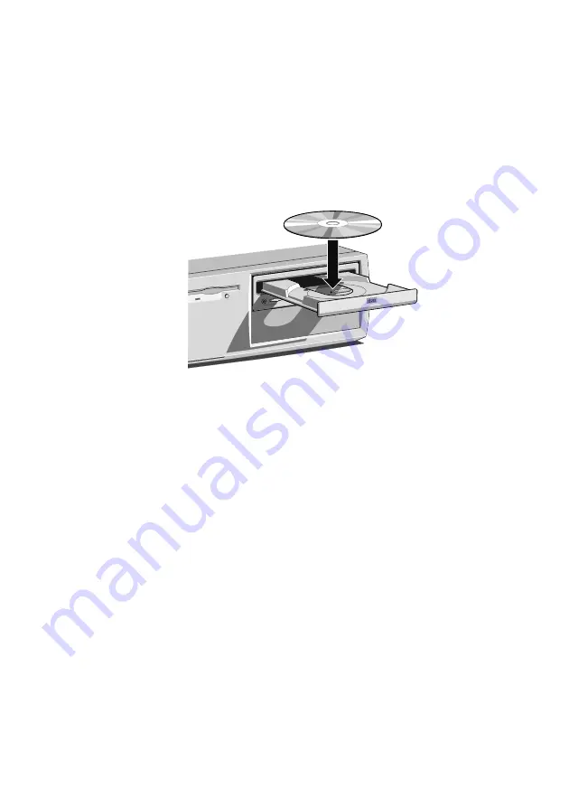
Inserting a compact disc

1.


Press the 

EJECT 

button on the front of drive.

2.


Place the CD centrally, printed side up, on the platter.

3.


Push the 

EJECT

 button again, or gently push the front of the

platter to draw it back into the drive.

COMPAC

T

Ejecting a compact disc


Ensure that the drive’s activity indicator is not showing ‘busy’,
then press the 

EJECT 

button.

To eject the platter manually (for example, during a power failure)
you must first ensure that the computer is completely off (the Power
Mode indicator will be unlit). Insert a thin metal rod (such as an
unwound paper clip) into the emergency eject hole. Push carefully
and firmly.

Summary of Contents for CX series

Page 1: ...COMPACT CX SERIES Owner s Handbook ...

Page 2: ...CX SERIES OWNER S HANDBOOK DESKTOP KL EDITION ...

Page 3: ...ware described in this manual is furnished under a license agreement The software may be used or copied only in accordance with the terms of this agreement It is against the law to copy any disk supplied for any purpose other than the purchaser s personal use No part of this manual may be reproduced or transmitted in any form or by any means electronic or mechanical including photocopying and reco...

Page 4: ...ains a lithium battery Do not use a metal or other conductive implement to remove the battery If a short circuit is made between its positive and negative terminals the battery may explode Replace a discharged battery with one of the same type another type may explode or ignite Follow the instructions contained in the Owner s Handbook to replace the battery Dispose of a discharged battery promptly...

Page 5: ... you should wear an earthed wrist strap and anti static clothing It is also a good idea to use an ionizer or humidifier to remove static from the air When installing any upgrade be sure you understand what the installation procedure involves before you start This will enable you to plan your work and so minimise the amount of time that sensitive components are exposed Do not remove the system unit...

Page 6: ...d run down inside the case and damage the circuitry Transporting Use common sense when handling the computer hard disks in particular can be damaged if the computer is dropped or handled roughly As a precaution back up the contents of the hard disks to tape or diskettes before moving the computer Switch off and disconnect all cables before attempting to move the computer particularly do not try to...

Page 7: ...ic Compatibility EMC This product complies with the following European EMC standards Emissions EN50022 Class B Immunity EN50082 1 This product also complies with the following International EMC standards VCCI Japan Class B Notes All interconnecting cables for example signal and communication cables should be less than 2 metres in length If cable extensions are used ensure adequate earth connection...

Page 8: ...lly sold you must check the voltage and frequency of that country s AC power supply and the type of power cord required there Check the power rating labels on the rear of the computer s system unit and its monitor to ensure that they are compatible with the AC power supply The computer can function within two alternative AC power supply ranges according to the position of the voltage selection swi...

Page 9: ...other appliance Then switch on or connect the AC power supply 4 Turn on the system unit first then the monitor then other peripherals Warning The Owners Handbook contains procedures which require opening of the system unit Ensure all cables including modem and network cables are disconnected before the system unit is opened Power Cable Connections UK ONLY This equipment is supplied with an AC powe...

Page 10: ...agement and Windows 2 2 Shutting down the PC 2 4 Using the computer for the first time 2 5 Backing up the pre installed software 2 5 Improving your display settings 2 6 If your hard disk is larger than 2 gigabytes 2 7 3 Diskettes and CDs Diskette drive 3 1 CD ROM drive optional 3 3 4 Expansion Cards Configuring the card 4 2 Installing the card 4 5 Reserving ISA legacy resources 4 6 Telling Windows...

Page 11: ...rt 5 4 On board video graphics controller 5 5 Additional A G P support 5 6 BIOS 5 7 PCI auto configuration 5 7 IDE auto configuration 5 7 ISA plug and play capability 5 7 Security passwords 5 8 Power management 5 8 Hardware monitor 5 10 Audio subsystem Optional 5 10 Upgrading components 5 12 The processor 5 12 How to install memory 5 15 How to replace the CMOS battery 5 18 How to clear the passwor...

Page 12: ...rive assembly 6 2 Fitting a 3 5 drive 6 3 Fitting a 5 25 drive 6 4 Reassembling the system 6 4 Configuring new drives 6 5 Partitioning and formatting hard disk drives 6 5 7 BIOS Setup POST Using the Setup utility 7 2 Setup modes 7 2 Starting Setup 7 3 If BIOS Setup starts on its own 7 3 Setup menus 7 4 Function keys 7 4 Maintenance menus 7 5 Main menu 7 6 Advanced menu 7 7 IDE configuration 7 11 F...

Page 13: ...menu 7 18 Exit menu 7 20 Upgrading the BIOS 7 21 Power on self test 7 24 Recoverable POST errors 7 24 Terminal POST errors and beep codes 7 27 8 Troubleshooting Problems when starting 8 1 If you suspect a blown fuse 8 1 Power on self test POST 8 2 Failure to boot 8 2 Common problems 8 3 Equipment Log ...

Page 14: ...tly comprises Windows for Workgroups 3 11 Windows 95 Windows 98 and Windows NT Warning Read the Safety Regulatory Notices section at the start of this manual before using the computer for the first time Unpacking After unpacking your computer keep all the cartons boxes and packaging materials you will need them again if you have to transport the computer elsewhere Use the page at the end of this m...

Page 15: ...ty indicator 3 CD ROM disc drawer platter 8 Power Mode indicator 4 CD activity indicator 9 POWER button 5 CD phono jack volume control Use the POWER button to turn on the computer and change power modes The Power Mode light on the button changes colour to show the current mode See the Getting Started chapter for more information Not all systems are fitted with a CD ROM drive ...

Page 16: ...AC power inlet from AC supply 11 Keyboard port 5 Audio input socket 12 Serial modem port 1 6 Microphone socket 13 Monitor port 7 Audio output socket for 14 Parallel printer port headphones or active speakers 15 Mouse port ones which connect to mains 16 Security loop for cable or padlock power only Do not connect 17 ISA or PCI slot passive non amplified speakers 18 3 PCI slots as damage to the moth...

Page 17: ...slightly then lift it off Refitting is the reverse of removal Take effective anti static precautions while the top cover is off as explained in the Safety Regulatory Notices at the start of this manual Some models incorporate a security feature that can detect if the top cover has been removed while the computer was turned off Optional DMI software such as Intel s LANDesk Client Manager is require...

Page 18: ... l c o m e OWNER S HANDBOOK 1 5 2 4 6 5 3 1 1 Configuration jumper 2 DIMM sockets for system memory upgrades 3 Processor socket Slot 1 4 Diskette drive 5 Battery 6 Drive assembly with optional CD ROM drive ...

Page 19: ... relating to ergonomic requirements For example you should ensure that little or no light is reflected off the monitor screen as glare and that the keyboard is placed in a comfortable position for typing Give the computer plenty of room so that air can circulate on all sides Air is drawn into the system unit through vents at the front and on the left hand side and expelled through the vent on the ...

Page 20: ...e connect the computer to the network 3 Connect the components power cords monitor to system unit and system unit and any other peripherals to nearby grounded AC power outlets Then switch on or connect the AC power supply With AC power applied the system unit is usually in Off mode LED unlit See the Getting Started chapter for more information about power modes Some models incorporate a feature co...

Page 21: ...emory During this time BIOS sign on and POST messages may be displayed These messages are not significant unless they report errors see the BIOS Setup POST chapter Booting the operating system Provided that POST succeeds without discovering any serious errors or configuration discrepancies the computer attempts to find an operating system that is it attempts to boot Mitsubishi Electric PCs are typ...

Page 22: ...r complies with the requirements of the Energy Star programme for energy saving systems In its Power Controlled state your computer does its best to reduce power usage but may not always reach Energy Star levels If a suitable modem is installed you can tell the computer to wake itself up from the Power Minimised or Off state when an incoming call is received A networked computer can also be woken ...

Page 23: ...lso configure the Control Panel Display applet to suppress or shut off power to the monitor after specified periods of inactivity In Windows 98 only you can configure the Control Panel Power applet to suppress power to the hard disk drives after a specified period of inactivity Outside Windows you can use the BIOS Setup utility to configure the computer to enter a Power Minimised Standby mode afte...

Page 24: ...er 3c In Windows 3 11 Windows for Workgroups click the File menu in Program Manager then click Exit Windows Once back in MS DOS press the POWER button 3d In MS DOS or during POST press the POWER button After you shut down the computer wait at least 5 seconds before turning it on again The computer may not initialise itself properly if you turn it off then on again in quick succession Emergency shu...

Page 25: ... continue By doing so you are acknowledging that you have read understood and accepted the terms and conditions Backing up the pre installed software We strongly recommend that you copy or back up the operating system and any pre installed software soon after setting up the system This is particularly important for systems that are supplied without installation diskettes for the software on the ha...

Page 26: ...t the best performance from it Display settings in Windows 95 98 or Windows NT The monitor setting is changed by using the Settings tab of the Display Properties dialog See Windows Help for instructions on changing display settings Tip To view the Display Properties dialog right click with the mouse while pointing at the background area of the Windows desktop then select Properties from the pop up...

Page 27: ...ows NT 4 0 the first 2 Gbytes are formatted using FAT as a primary partition The rest of the disk is untouched You can re partition and reformat the disk using the Disk Administrator tool in the Administrative Tools Common folder If you have Windows 3 11 Windows for Workgroups the first 2 Gbytes are formatted as the primary partition The remainder of the disk is divided into formatted partitions o...

Page 28: ...gerprint that might make the diskette difficult to read Keep diskettes away from dust moisture magnetic objects and equipment that generates magnetic fields Also avoid extremes of temperature and exposure to direct sunlight Otherwise data recorded on the diskette may become corrupted Inserting a diskette 1 Insert the diskette with the metal shutter foremost and with the label side facing upwards C...

Page 29: ...peeled back do not attempt to remove it with tweezers or any similar implement you risk damaging the drive Call an authorised maintainer Write protecting a diskette A diskette can be write protected by sliding a tab towards the edge of the diskette to expose the small hole beneath it see illustration You can read copy or print the files on a write protected diskette but you cannot create rename or...

Page 30: ...temperature and exposure to direct sunlight as these may cause the disc to warp COMPAC T 2 3 4 5 1 1 CD ROM disc drawer platter 2 Headphone jack volume control 3 Activity indicator amber busy 4 CD emergency eject hole 5 EJECT button doesn t work while PC is turned off Do not attempt to move the computer while a CD is in the drive especially if the CD is being played at the time Warning The laser b...

Page 31: ...e platter to draw it back into the drive COMPACT Ejecting a compact disc Ensure that the drive s activity indicator is not showing busy then press the EJECT button To eject the platter manually for example during a power failure you must first ensure that the computer is completely off the Power Mode indicator will be unlit Insert a thin metal rod such as an unwound paper clip into the emergency e...

Page 32: ...cards PCI or Peripheral Component Interconnect cards You don t need to understand what these terms mean but before adding a card to your computer you will need to know whether it is ISA or PCI and possibly its physical dimensions The following diagram shows the layout of the expansion slots in your PC as viewed from the rear PCI half length 1 PCI half length 2 PCI full length 3 Shared PCI or ISA f...

Page 33: ...ress The important thing to understand is that the settings of the card you are installing must be different from the settings used by other cards already in the computer or by components on the computer s motherboard In other words the settings must not conflict The documentation accompanying the card should tell you whether the card supports Plug and Play or if not how to configure it Remember t...

Page 34: ...one of these devices an alternative interrupt will be assigned through Plug and Play and the original interrupt can instead be used by the expansion card See the BIOS Setup POST chapter for more information about BIOS Setup See the Motherboard chapter for more information about jumper settings and the usual assignment of interrupts to motherboard components Direct memory access DMA channel Some ha...

Page 35: ...UMB regions with the BIOS Setup utility The card s documentation should list its possible base memory addresses You may also need to know how much memory the card has so that you can leave the right gap between this card s base address and the next More about memory addresses Memory addresses are always written in base 16 or hexadecimal notation Unlike the ten digits of the decimal system 0 9 hexa...

Page 36: ...ly tool required is a small cross head screwdriver 1 Observe the precautions detailed in the Safety and Regulatory notices at the front of this handbook 2 Turn off and disconnect all peripheral devices connected to the computer Then turn off the computer and remove the power cord 3 Decide in which of the available slots you wish to install the card In general it is easiest where possible to start ...

Page 37: ... the bottom two slots may require the temporary removal of the processor see the Motherboard chapter for details 7 Slide the card into the slot ensuring that the card edge connector engages correctly with the socket on the NLX riser board Do not use excessive force 8 Secure the card by replacing the screw that you removed in Step 4 9 Connect any necessary signal cables to the card 10 Ensure no oth...

Page 38: ... you cannot change its resources or it isn t using any resource settings 6 Click the resource you want to change un check the Use Automatic Settings box then click Change Setting Tip In some cases you may see a Set Configuration Manually button on the Resources tab You may have to click this button before you can change resource settings Telling Windows about the new hardware Windows 95 98 should ...

Page 39: ...ts with static electricity Features summary NLX form factor of 33 x 22 8 cm with four mounting screw holes Support for a single Pentium II processor 66 MHz and 100 MHz host bus speeds Slot 1 connector Integrated 512 KB second level cache Three DIMM sockets Supports up to 384 MB of synchronous DRAM SDRAM memory Intel 82440BX AGPset PCI A G P controller PAC PCI ISA IDE Xcelerator PIIX4E I O controll...

Page 40: ...er J5G1 8 DIMM sockets 4 CMOS battery 9 A G P connector 5 Piezoelectric speaker optional Caution Care must be taken in the purchase of upgrade parts to ensure both compatibility with the system and the compliance with appropriate approvals and certification e g CE marking within Europe Using non approved parts may invalidate your warranty and system approvals It may also cause damage to other comp...

Page 41: ...nboard memory is cacheable PCI enhanced IDE interface The PCI enhanced IDE interface handles the exchange of information between the processor and peripheral devices like hard disks and add in boards inside the computer The interface supports Up to four IDE devices such as hard drives ATAPI devices PIO mode 3 and PIO mode 4 devices Logical block addressing LBA of hard drives larger than 528 MB and...

Page 42: ...tenance feature that checks the least two significant digits of the year stored in the RTC during each BIOS request INT 1Ah to read the date and if less than 80 i e 1980 is the first year supported by the PC updates the century byte to 20 This feature enables operating systems and applications using the BIOS date time services to reliably manipulate the year as a four digit value Universal Serial ...

Page 43: ... shielded cable that meets the requirements for a full speed USB device If in doubt consult your supplier or the device manufacturer On board video graphics controller The on board ATI Rage Pro 2x graphics controller provides these features 1x 66MHz and 2x 133MHz fully pipelined operation and sideband support Full bus mastering support Triple 8 bit palette DAC with gamma correction pixel rates up ...

Page 44: ...g for flipping video images in video conferencing systems Bi directional bus mastering engine with planar YUV to packed format converter YUV to RGB colour space converter with support for both packed and planar YUV YUV 4 2 2 YUV 4 1 0 and YUV 4 2 0 RGB 32 RGB 16 15 RGB 8 and monochrome Additional A G P support The A G P is a high performance interconnect for graphics intensive applications such as...

Page 45: ...ll a PCI add in board However PCI add in boards use the same IRQ resources as ISA add in boards If you install both a PCI and an ISA add in board you must specify the IRQ used by the ISA card The PCI auto configuration program complies with version 2 1 of the PCI BIOS specification IDE auto configuration If you install an IDE device e g a hard drive in your computer the IDE auto configuration util...

Page 46: ...rompt of the Setup program gives the user restricted access to Setup If both the supervisor and user passwords are set you must enter either the supervisor password or the user password to access Setup Setting a user password restricts who can boot the computer The password prompt is displayed before the computer is booted If only the supervisor password is set the computer boots without asking fo...

Page 47: ...indows 95 supports the power management features upon detecting that APM is enabled in the BIOS Advanced Configuration and Power Interface ACPI ACPI gives the operating system direct control over the power management and Plug and Play functions of a computer ACPI requires an ACPI aware operating system ACPI features include Plug and Play including bus and device enumeration and APM functionality n...

Page 48: ...r voltage are exceeded an interrupt is activated The hardware monitor component connects to the system management SM bus Audio subsystem Optional The optional audio subsystem consists of the following Crystal Semiconductor CS4235 audio codec Back panel and onboard audio connectors Crystal Semiconductor CS4235 audio codec The CS4235 audio codec s features include Compatibility with Sound Blaster So...

Page 49: ...M o t h e r b o a r d OWNER S HANDBOOK 5 11 Speaker Optional A piezoelectric speaker can be mounted on the motherboard The speaker provides audible error code beep code information during the POST ...

Page 50: ... detailed in the Safety and Regulatory Notices at the front of this handbook 2 Turn off and disconnect all peripheral devices connected to the computer Then turn off the computer and remove the power cord 3 Remove the computer cover 4 Remove the heatsink support if one is fitted from the base as shown in the following illustration Then press in on the latches to release the top bar A 1 2 1 2 B A H...

Page 51: ...may have a fan fitted in which case connect the fan lead to the fan connector 4 Set the processor speed in the BIOS Setup as detailed in the following procedure How to set the processor speed Set the processor speed immediately after you have installed or upgraded the processor You can perform the first steps while you still have the system open 1 Locate the configuration jumper from the illustrat...

Page 52: ... Enter to confirm the speed This Maintenance menu reappears again 7 Press F10 to save the current values and exit Setup 8 Turn off the computer and remove the power cord 9 Remove the computer cover 10 To restore normal operation place the jumper on pins 1 2 as shown below 11 Replace the cover and turn on the computer 12 Verify the processor speed during POST ...

Page 53: ...onfiguration 8 MB 1 Mbit x 64 1 Mbit x 72 16 MB 2 Mbit x 64 2 Mbit x 72 32 MB 4 Mbit x 64 4 Mbit x 72 64 MB 8 Mbit x 64 8 Mbit x 72 128 MB 16 Mbit x 64 16 Mbit x 72 When adding memory follow these guidelines You can install DIMMs in any of the three banks You can use different sizes of DIMMs in different banks The BIOS detects the size and type of installed memory Notes For ECC operation to be ava...

Page 54: ...the DIMM sockets using the illustration on page 2 of this chapter 4 Holding the DIMM by the edges remove it from its antistatic package 5 Make sure the clips at either end of the socket are pushed away from the socket 6 Position the DIMM above the socket Align the two small notches in the bottom edge of the DIMM with the keys in the socket 7 Insert the bottom edge of the DIMM into the socket 8 Whe...

Page 55: ... the front of this handbook 2 Turn off and disconnect all peripheral devices connected to the computer Then turn off the computer and remove the power cord 3 Remove the computer cover 4 Gently spread the retaining clips at each end of the socket The DIMM pops out of the socket 5 Hold the DIMM by the edges lift it away from the socket and store it in an antistatic package ...

Page 56: ...turer s instructions To replace the battery follow these steps 1 Observe the precautions detailed in the Safety and Regulatory Notices at the front of this handbook 2 Turn off and disconnect all peripheral devices connected to the computer Then turn off the computer and remove the power cord 3 Remove the computer cover To get clear access to the battery you may have to remove the system processor ...

Page 57: ...ng the illustration on page 2 of this chapter 5 Place the jumper on pins 2 3 as shown below 6 Replace the cover turn on the computer and allow it to boot 7 The computer starts the Setup program Setup displays the Maintenance menu 8 Use the arrow keys to select Clear Passwords Press Enter and Setup displays a pop up screen requesting that you confirm clearing the password Select Yes and press Enter...

Page 58: ...entional memory DMA channels DMA Channel Number Data Width System Resource 0 8 or 16 bits Audio 1 8 or 16 bits Audio parallel port 2 8 or 16 bits Diskette drive 3 8 or 16 bits Parallel port for ECP audio 4 Reserved cascade channel 5 16 bits Open 6 16 bits Open 7 16 bits Open I O map Address hex Size Description 0000 000F 16 bytes DMA controller 1 0020 0021 2 bytes Interrupt controller 1 002E 002F ...

Page 59: ...4A 02F8 02FF 8 bytes COM2 0330 0331 2 bytes MPU 401 MIDI 0376 0377 2 bytes Secondary IDE controller 0120 0127 8 bytes Audio controller 0274 0277 4 bytes I O read data port for ISA Plug and Play enumerator 0378 037F 8 bytes LPT1 0388 038D 6 bytes AdLib FM synthesizer 03B0 03BB 12 bytes Video monochrome 03C0 03DF 32 bytes Video VGA 03E8 03EF 8 bytes COM3 03F0 03F5 03F7 7 bytes Diskette controller 03...

Page 60: ... slot 2 on the riser 00 0F 00 PCI expansion slot 3 on the riser 00 10 00 PCI expansion slot 4 on the riser Interrupts IRQ System Resource NMI I O channel check 0 Reserved interval timer 1 Reserved keyboard buffer full 2 Reserved cascade interrupt from slave PIC 3 COM2 4 COM1 5 LPT2 Plug and Play option audio user available 6 Diskette drive controller 7 LPT1 8 Real time clock 9 Reserved 10 USB User...

Page 61: ...of three E IDE drives The first drive which contains the operating system is always configured as the master drive Other drives must be configured as slave devices Drives are normally configured as master or slave by using jumpers on the drive itself Configuration details vary from drive to drive Most drives are supplied with documentation describing how to configure the drive If you are uncertain...

Page 62: ... diskette in the diskette drive remove it 3 Take suitable anti static precautions and remove the system unit cover For more information see Anti static precautions in the Safety Regulatory Notices at the start of this manual 4 Disconnect the power and ribbon cables from the rear of all the drives fitted in the drive assembly Take careful note of how and where they are connected you will need to re...

Page 63: ...ing plate behind it Fitting a 3 5 drive The drive bay is designed for 5 25 drives If you intend to fit a 3 5 device such as a hard disk drive you must first fit a 3 5 drive bay adapter such as the one shown below These are generally available from PC hardware suppliers 1 Fit the new drive into the adapter using the special screws provided Do not overtighten the screws and put a strain on the drive...

Page 64: ...t overtighten the screws and put a strain on the drive casing CDcaddy COMPA CT Reassembling the system 1 Put the drive assembly back into the system unit and tighten the screws to secure it to the chassis 2 Re attach the power and signal cables to the original drives and the riser board Connect a spare power cable and the spare connector on the ribbon cable between the new drive and the riser boar...

Page 65: ...nk Before you can use the drive you must partition and format it Windows 95 98 Use the MS DOS Fdisk program to create partitions on the disk The Fdisk program can be run in an MS DOS window within Windows Type Help Fdisk at the MS DOS command prompt to find out more After using Fdisk you are prompted to restart the computer Once back in Windows you can format the partitions by opening the My Compu...

Page 66: ... about Fdisk and Format See your MS DOS documentation for instructions on using MS DOS Help A limitation of Windows for Workgroups is that each partition can be no more than 2 gigabytes in size Caution When you run Fdisk it assumes that you want to work with the first or master drive it says the Current fixed disk drive is 1 To switch attention to the slave drive choose Select next fixed disk driv...

Page 67: ... the software you use can recognise and exploit the hardware s capabilities The current configuration is kept in a special area of memory called CMOS memory and maintained by a battery so that the configuration is preserved even while the computer is switched off Your computer arrives already configured but may need to be configured again after you add or remove add on options such as memory modul...

Page 68: ...d chapter for how to do both tasks Recovery mode for recovering the BIOS data The Setup utility operating mode is controlled by the setting of the configuration jumper block J5G1 see page 1 5 The jumper is set to Normal mode at the factory The following table shows jumper settings for the different Setup modes Mode Jumper Description Normal 1 2 BIOS uses current configuration and passwords for boo...

Page 69: ... on self test POST detects a configuration error or fault This may be signalled by one or more POST error messages If a persistent fault is indicated make a note of any error messages and the current configuration settings before calling an authorised maintainer The CMOS battery may be running down This may cause spurious POST error messages If this happens every time you turn on the computer you ...

Page 70: ... options and power supply controls Exit Saves or discards changes to the Setup utility options Function keys The following table shows the function keys available for menu screens Setup Key Description F1 or Alt H Brings up a help screen for the current item Esc Exits the menu or Selects a different menu screen or Moves cursor up or down Home or End Moves cursor to top or bottom of the window PgUp...

Page 71: ...in this chapter for information about setting Configure mode Feature Options Description Processor Speed 233 266 300 333 350 400 450 Specifies the processor speed in megahertz With a host bus operating at 66 MHz the board supports processors at 233 266 300 and 333 MHz With a host bus operating at 100 MHz the board supports processors at 350 400 and 450 MHz Clear All Passwords No options Clears the...

Page 72: ...ys size of second level cache System Memory No options Displays the total amount of RAM on the motherboard Memory Bank 0 Memory Bank 1 Memory Bank 2 No options Displays size and type of DIMM installed in each memory bank Language English Francais Italiano Deutch Espanol Selects the default language used by the BIOS ECC Configuration Non ECC ECC Specifies ECC memory operation L2 Cache ECC Support E...

Page 73: ...ower on state of the Num Lock feature on the numeric keypad of the keyboard Peripheral Configuration Sub menu Configures peripheral ports and devices When selected displays the Peripheral Configuration submenu IDE Configuration Sub menu Specifies type of connected IDE device Floppy Configuration Sub menu When selected displays the Floppy Options submenu DMI Events Logging Sub menu Configures DMI E...

Page 74: ...E8 2E8 Specifies the base I O address for serial port A Interrupt IRQ 3 IRQ 4 Specifies the interrupt for serial port A Serial port B Disabled Enabled Auto Configures serial port B Auto assigns the first free COM port normally COM2 the address 2F8h and the interrupt IRQ3 An asterisk displayed next to an address indicates a conflict with another device If either serial port address is set that addr...

Page 75: ... LPT1 the address 378h and the interrupt IRQ7 An asterisk displayed next to an address indicates a conflict with another device Mode Output Only Bi directional EPP ECP Selects the mode for the parallel port Output Only operates in AT compatible mode Bi directional operates in bi directional PS 2 compatible mode EPP is Extended Parallel Port mode a high speed bi directional mode ECP is Enhanced Cap...

Page 76: ...nabled Enables or disables the onboard audio subsystem LAN Disabled Enabled Enables or disables the configuration of the LAN device Embedded PXE Support Disabled Enabled Enables or disables LANDesk service agent option Legacy USB Support Disabled Enabled Enables or disables USB legacy support ...

Page 77: ...s 12 Seconds 15 Seconds 21 Seconds 30 Seconds Specifies the hard disk drive pre delay Primary IDE Master No options Reports type of connected IDE device When selected displays the Primary IDE Master submenu Primary IDE Slave No options Reports type of connected IDE device When selected displays the Primary IDE Slave submenu Secondary IDE Master No options Reports type of connected IDE device When ...

Page 78: ...s to be changed Auto automatically fills in the values for the cylinders heads and sectors fields Maximum Capacity No options Reports the maximum capacity for the hard disk Multi Sector Transfers Disabled 2 Sectors 4 Sectors 8 Sectors 16 Sectors Specifies number of sectors per block for transfers from the hard drive to memory Check the hard drive s specifications for optimum setting LBA Mode Contr...

Page 79: ...kette A Disabled 360 KB 5 1 2 MB 5 720 KB 3 1 44 1 25 MB 3 2 88 MB 3 Specifies the capacity and physical size of diskette drive A Floppy Write Protect Disabled Enabled Disables or enables write protect for the diskette drive DMI Event Logging This submenu is for configuring the DMI event logging features Feature Options Description Event log capacity No options Indicates if there is space availabl...

Page 80: ...abled Enables logging of ECC events Mark DMI events as read No options Marks all DMI events as read Video Configuration submenu This submenu is for configuring video features Feature Options Description Palette Snooping Disabled Enabled Controls the ability of a primary PCI graphics controller to share a common palette with an ISA add in video card AGP Aperture Size 64 MB 256 MB Specifies the aper...

Page 81: ...0 DBFF Available Reserved DC00 DFFF Available Reserved Reserves specific upper memory blocks for use by legacy ISA devices Memory hole Disabled Conventional Extended Memory hole frees address space in RAM for a legacy ISA board IRQ Reservation IRQ3 Available Reserved IRQ4 Available Reserved IRQ5 Available Reserved IRQ7 Available Reserved IRQ10 Available Reserved IRQ11 Available Reserved Reserves s...

Page 82: ...eric characters Specifies the user password Set Supervisor Password Password can be up to seven alphanumeric characters Specifies the supervisor password Clear User No Options Clears the user password User Setup Access None View Only Limited Access Full Enables or disables User Setup Access None prevents the user from accessing Setup Unattended Start Disabled Enabled Enables the unattended start f...

Page 83: ... management feature Inactivity Timer Off 1 Minute 5 Minutes 10 Minutes 20 Minutes 30 Minutes 60 Minutes 120 Minutes Specifies the amount of time before the computer enters Standby mode Hard Drive Disabled Enabled Enables power management for hard disks during Standby and Suspend modes VESA Video Power Down Disabled Standby Suspend Sleep Specifies power management for video during Standby and Suspe...

Page 84: ...ower On Stay Off Last State Specifies the mode of operation if an AC Power loss occurs Power On restores power to the computer Stay Off keeps the power off until the power button is pressed Last State restores the previous power state before power loss occurred On Modem Ring Stay Off Power On Specifies how the computer responds to an incoming call on an installed modem when the power is off On LAN...

Page 85: ...e order of the devices changes the drive lettering Hard Drive No options Lists available hard drives When selected displays the Hard Drive submenu Removable Devices No options Lists available removable devices When selected displays the Removable Devices submenu Hard drive submenu This submenu is for configuring the boot sequence for hard drives Options Description Bootable Add in Card Specifies t...

Page 86: ... menu is for exiting the Setup utility saving changes and loading and saving defaults Feature Description Exit Saving Changes Exits and saves the changes in CMOS RAM Exit Discarding Changes Exits without saving any changes made in Setup Load Setup Defaults Loads the factory default values for all the Setup options Load Custom Defaults Loads the custom defaults for Setup options Save Custom Default...

Page 87: ...stem files 3 Copy the BIOS upgrade file to an empty directory on the computer s hard disk 4 Open an MS DOS window change to the directory containing the BIOS upgrade file and then execute it The contents of the upgrade file are extracted including license txt bioinstr txt and bios exe 5 Read the software licence agreement contained in license txt and the additional upgrade instructions contained i...

Page 88: ... interrupt the BIOS upgrade however if an interruption occurs the BIOS could be damaged The following steps explain how to recover the BIOS if an upgrade fails The following procedure uses Recovery mode for the Setup utility Setup modes are described earlier in this chapter Note Because of the small amount of code available in the non erasable boot block area there is no video support You will not...

Page 89: ...g the power cord 8 Remove the system unit cover 9 Return the jumper to pins 1 2 of jumper block J5G1 to set Normal mode for Setup 1 3 J5G1 OM08177 10 Leave the upgrade diskette in drive A replace the computer cover and re connect the power cord 11 Turn on the computer and continue with the BIOS upgrade procedure To change the BIOS language You can use the BIOS upgrade utility to change the languag...

Page 90: ... error message describing the problem the most usual are described below After some messages you may be prompted to Press F1 key to resume F2 to run Setup or just Press F2 key if you want to run Setup In general you should respond to these errors as follows Shut down the computer wait 20 to 30 seconds and then turn it on again to see if the problem is still reported Check that all external cables ...

Page 91: ...working or not configured properly Check to see if fixed disk is installed properly Run Setup to be sure the fixed disk type is correctly identified Incorrect Drive A type run SETUP Type of diskette drive for drive A not correctly identified in Setup Invalid NVRAM media type Problem with NVRAM CMOS access Keyboard controller error The keyboard controller failed test Try replacing the keyboard Keyb...

Page 92: ...Failed at offset nnnn Shadow RAM failed at offset nnnn of the 64 KB block at which the error was detected System battery is dead Replace and run SETUP The CMOS clock battery indicator shows the battery is dead Replace the battery and run Setup to reconfigure the system System cache error Cache disabled RAM cache failed the BIOS test BIOS disabled the cache System CMOS checksum bad run SETUP System...

Page 93: ...orised maintainer Beeps Port 80h Code Explanation 1 2 2 3 16h BIOS ROM checksum 1 3 1 1 20h Test DRAM refresh 1 3 1 3 22h Test Keyboard Controller 1 3 3 1 28h Autosize DRAM 1 3 3 2 29h Initialize POST Memory Manager 1 3 3 3 2Ah Clear 512 KB base RAM 1 3 4 1 2Ch RAM failure on address line xxxx 1 3 4 3 2Eh RAM failure on data bits xxxx of low byte of memory bus 1 4 1 1 30h RAM failure on data bits ...

Page 94: ...lure on address line xxxx 1 3 4 3 2Eh RAM failure on data bits xxxx of low byte of memory bus 1 4 1 1 30h RAM failure on data bits xxxx of high byte of memory bus 2 1 2 2 45h POST device initialization 2 1 2 3 46h Check ROM copyright notice 2 2 3 1 58h Test for unexpected interrupts 2 2 4 1 5Ch Test RAM between 512 and 640 KB 1 2 98h Search for option ROMs One long two short beeps on checksum fail...

Page 95: ...r cords before consulting your supplier or maintenance provider Problems when starting If you suspect a blown fuse In the United Kingdom and some other countries AC plugs contain fuses If the fuse in the system s unit AC plug blows when you turn on the computer this may be caused by an AC power surge but is more often a symptom of problems with the computer or its peripherals Follow these steps 1 ...

Page 96: ...Either remove it or replace it with a system diskette and press F1 Diskette read failure The diskette is either not formatted or defective Either remove it or replace it with a system diskette and press F1 No boot sector on fixed disk The hard disk has no active bootable partition or is not formatted If you are still using the original master hard disk drive supplied with your computer this is a s...

Page 97: ... of common problems Connections Check that all power and signal cables are securely connected to the correct port on the computer The keyboard and mouse are particularly easy to connect into the wrong port Although the connectors are identical the keyboard will not work if plugged into the mouse port and vice versa Power Check that the AC power supply is switched on and that the fuse in the AC plu...

Page 98: ...r If the liquid is thin and clear try unplugging the keyboard turning it upside down to let the liquid drain out and drying it for at least 24 hours at room temperature If the keyboard still won t work call your supplier or maintenance provider Expansion cards If an expansion card does not work check that all internal cables are securely connected that the card is configured correctly that its use...

Page 99: ... ROM drive If you have problems accessing a CD check that you have allowed a few seconds for the disk to spin up to full speed that the disk is the correct way up in the drive printed side upwards and that it is a data CD Remember that with a conventional CD ROM drive you cannot write to a CD Hard disk drives If you encounter problems accessing a hard disk drive use the BIOS Setup utility to check...

Page 100: ...about your PC Passwords Software Password Manufacturer s data You should record the model codes and serial numbers of the system components Model Serial number System unit Monitor Keyboard Mouse Expansion card 1 Expansion card 2 Expansion card 3 Expansion card 4 ...

Page 101: ...ISION 3500 Parkside Birmingham Business Park Birmingham B37 7YS United Kingdom Tel 44 0 121 717 7171 Fax 44 0 121 717 7799 MITSUBISHI ELECTRIC PC DIVISION Niederlassung Deutschland Gothaer Strasse 27 40880 Ratingen Germany Tel 49 0 2102 4556 Fax 49 0 2102 455700 ...

Reviews: