background image

8

EN

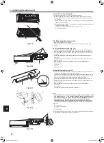
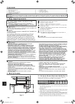
4.  Installing the refrigerant piping

Fig. 4-4

B

A

D

C

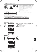
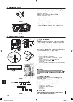
4.3.  Refrigerant piping (Fig. 4-3)

Indoor unit

1. Remove the flare nut and cap of the indoor unit.

2. Make a flare for the liquid pipe and gas pipe and apply refrigerating machine oil 

(available from your local supplier) to the flare sheet surface.

3. Quickly connect the on site cooling pipes to the unit. 

4. Wrap the pipe cover that is attached to the gas pipe and make sure that the 

connection join is not visible.

5. Wrap the pipe cover of the unit’s liquid pipe and make sure that it covers the 

insulation material of the on site liquid pipe.

6. The portion where the insulation material is joined is sealed by taping.

Site-side refrigerant piping

Unit side refrigerant piping

4.3.1.  Storing in the piping space of the unit (Fig. 4-4)

1. Wrap the supplied felt tape in the range of the refrigerant piping which will be 

housed within the piping space of the unit to prevent dripping.

2. Overlap the felt tape at one-half of the tape width.

3. Fasten the end portion of the wrapping with vinyl tape, etc.

Gas pipe

B

  Liquid pipe

C

  Indoor/outdoor connection cable

D

  Felt tape 

3

Fig. 4-3

B

A

Fig. 5-1

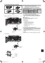
5.  Drainage piping work

A

B

C

E

D

C

F

C

G

H

I

J

K

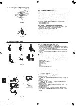
5.1.  Drainage piping work (Fig. 5-1)

•  Drain pipes should have an inclination of 1/100 or more.

•  For extension of the drain pipe, use a soft hose (inner dia. 15 mm) available on 

the market or hard vinyl chloride pipe (VP-16/O.D. ø22 PVC TUBE).  Make sure 

that there is no water leakage from the connections.

•  Do not put the drain piping directly in a drainage ditch where sulphuric gas may 

be generated.

•  When piping has been completed, check that water flows from the end of the 

drain pipe.

 Caution:

The drain pipe should be installed according to this Installation Manual to 

ensure correct drainage. Thermal insulation of the drain pipes is necessary 

to prevent condensation. If the drain pipes are not properly installed and 

insulated, condensation may drip on the ceiling, floor or other possessions.

Inclined downwards

Must be lower than outlet point

Water leakage

Trapped drainage

Air

Wavy

The end of drain pipe is under water.

Drainage ditch

I

  5 cm or less between the end of drain pipe and the ground.

Drain hose

Soft PVC hose (Inside diameter 15 mm)  
or  
Hard PVC pipe (VP-16) 
* Bond with PVC type adhesive 

Preparing left and left rear piping (Fig. 5-2)

Remove the drain cap.

•  Remove the drain cap by holding the bit that sticks out at the end of the pipe and 

pulling.

Drain cap

Remove the drain hose.

•  Remove the drain hose by holding on to the base of the hose 

a

 (shown by 

arrow) and pulling towards yourself 

b

.

Insert the drain cap.

•  Insert a screwdriver etc into the hole at the end of the pipe and be sure to push 

to the base of the drain cap.

Insert the drain hose.

•  Push the drain hose until it is at the base of the drain box connection outlet.

•  Please make sure the drain hose hook is fastened properly over the extruding 

drain box connection outlet.

Hooks

A

A

1

3

Fig. 5-2

a

b

A

B

2

4

RH79A015H01_en.indd   8

2019/02/01   16:14:05

Summary of Contents for CITY MULTI PKFY-P VLM Series

Page 1: ...новке до выполнения установки кондиционера ДЛЯ УСТАНОВИТЕЛЯ English EN INSTALLATION MANUAL For safe and correct use please read this installation manual thoroughly before installing the air conditioner unit FOR INSTALLER For use with the R410A Для использования с моделями R410A R410A ile beraber kullanmak için Türkçe TR MONTAJ ELKİTABI Emniyetli ve doğru kullanım için klima cihazını monte etmeden ...

Page 2: ...і а потім мову BG Посетете горепосочения уебсайт за да изтеглите ръководства като изберете име на модел и след това език PL Odwiedź powyższą stronę internetową aby pobrać instrukcje wybierz nazwę modelu a następnie język CS Příručky naleznete ke stažení na internetové stránce zmíněné výše poté co zvolíte model a jazyk SK Na webovej stránke vyššie si môžete stiahnuť návody Vyberte názov modelu a zv...

Page 3: ...rly qualified persons in order to avoid a hazard 1 Safety precautions Indicates an action that must be avoided Indicates that important instructions must be followed Indicates a part which must be grounded Indicates that caution should be taken with rotating parts Indicates that the main power switch must be turned off before servicing Beware of electric shock Beware of hot surface ELV At servicin...

Page 4: ...g contractor Fig 3 2 Fig 3 3 A Mount board 1 B Indoor unit C Bottom left rear pipe hole ø75 D Bottom right rear pipe hole ø75 E Knockout hole for left rear hole P10 15 20 25 32 105 215 P40 50 105 300 F Bolt hole 4 ø9 hole G Tapping hole 6 ø4 3 hole H Hole centre I Align the scale with the line J Insert scale 3 2 2 Drilling the piping hole Fig 3 4 Use a core drill to make a hole of 75 80 mm diamete...

Page 5: ...ng on the mount board as a reference when adjusting the length of the embedded cooling pipe During construction give the length of the extruding pipes etc some leeway A Mount board 1 B Reference marking for flare connection C Through hole D On site piping 3 4 Preparing the indoor unit Check beforehand because the preparatory work will differ depending on the exiting direction of the piping When be...

Page 6: ...indoor unit is installed level A Mount board 1 B Indoor unit C Hook D Square hole Left and left rear piping Fig 3 12 3 While inserting the drain hose into the wall penetration hole penetration sleeve hang the top of the indoor unit to the mount board 1 Cut part of the shipping box and wrap into a cylindrical form as illustrated in the diagram Hook this to the rear surface rib as a spacer and raise...

Page 7: ...t Use two wrenches to tighten piping connections Use refrigerant piping insulation provided to insulate indoor unit connections Insulate carefully Do not apply refrigerating machine oil to the screw portions This will make the flare nuts more apt to loosen Use flare nut installed to this indoor unit Warning When installing the unit securely connect the refrigerant pipes before starting the compres...

Page 8: ...2 PVC TUBE Make sure that there is no water leakage from the connections Do not put the drain piping directly in a drainage ditch where sulphuric gas may be generated When piping has been completed check that water flows from the end of the drain pipe Caution The drain pipe should be installed according to this Installation Manual to ensure correct drainage Thermal insulation of the drain pipes is...

Page 9: ...ut 3 Install the parts that were removed back to their original condition 4 Fasten each of the wires with the clamp under the electrical parts box A Electrical box cover B Fixing screw C Clamp D Ground wire connection portion E MA remote control terminal block 1 2 do not have polarity F Transmission terminal block M1 M2 S do not have polarity G Power supply terminal block L N H Terminal screw I Gr...

Page 10: ...ping time 0 01 s Please pick up C from the tripping characteristic of the breaker Example of F2 calculation Condition PEFY VMS 4 PEFY VMA 1 C 8 refer to right sample chart F2 19 8 4 8 38 1 8 14 65 16 A breaker Tripping current 8 16 A at 0 01 s 3 Current sensitivity is calculated using the following formula G1 V2 Quantity of Type1 V2 Quantity of Type2 V2 Quantity of Type3 V2 Quantity of Others V3 W...

Page 11: ...etting of indoor unit and wireless remote control ler Pair No is 0 A Terminal block for indoor transmission cable B Terminal block for outdoor transmission cable M1 A M2 B S C Remote controller D Wireless signal receiver E Wireless remote controller 6 5 Setting addresses Fig 6 4 Be sure to operate with the main power turned OFF There are two types of rotary switch setting available setting address...

Page 12: ...ursor down 8 Function button F2 Main display Press to decrease temperature Main menu Press to move the cursor up 9 Function button F3 Main display Press to increase temperature Main menu Press to go to the previous page 0 Function button F4 Main display Press to change the fan speed Main menu Press to go to the next page Controller interface Fig 7 1 Step 1 Switch the remote controller to Test run ...

Page 13: ...h the operation modes in the order of Cool and Heat Fig 7 5 Cool mode Check the cold air blow off Heat mode Check the heat blow off Check the operation of the outdoor unit s fan 2 Press the button and open the Vane setting screen AUTO vane check 1 Check the auto vane with the F1 F2 buttons Fig 7 6 2 Press the button to return to Test run operation 3 Press the button 7 Test run RH79A015H01_en indd ...

Page 14: ...вреждения в шнуре питания его следует заменить у производителя или его сервисного представителя или у лица аналогичной квалификации во избежание опасной ситуации 1 Меры предосторожности Указывает действие которое следует избегать Указывает на важную инструкцию Указывает что данная часть должна быть заземлена Указывает на необходимость проявлять осторожность по отношению к вращающимся частям Указыв...

Page 15: ...ть линейку с линией J Вставить линейку 3 2 2 Сверление отверстия для труб Fig 3 4 Используя трубчатое сверло просверлите отверстие диаметром 75 80 мм в стене в направлении труб в месте указанном на схеме слева Отверстие должно быть наклонным так чтобы наружное отверстие было ниже чем внутреннее отверстие Проведите рукав диаметром 75 мм приобретается на месте через отверстие Примечание Наклонность ...

Page 16: ...уть и обрезать под установку При обрезке встроенной трубки охлаждения используйте метки на монтажной плите Во время монтажных работ оставляйте запас трубок по длине A Монтажная плита 1 B Метки для фланцевых соединений C Через отверстие D Трубки монтируемые на месте 3 4 Подготовка внутреннего блока Поверьте заблаговременно поскольку подготовительные работы будут отличаться в зависимости от направле...

Page 17: ...ерстие на стене муфту подвесьте верхнюю часть внутреннего блока к монтажной плите 1 Отрежьте часть упаковочной коробки и сверните ее в цилиндр как показано на схеме Установите получившуюся трубку на ребро задней поверхности в качестве проставки затем поднимите внутренний блок 4 Подсоедините трубку хладагента к установленному на месте холодильному контуру 5 Закрепите блок вдвинув его нижнюю часть в...

Page 18: ... гаек Используйте раструбную гайку установленную на данный внутренний прибор Предупреждение При установке прибора надежно подсоедините трубы подачи охлаждаю щей жидкости до запуска компрессора A Раструбный стык размеры Медная труба O D мм Размеры раструба диаметр А мм ø6 35 8 7 9 1 ø9 52 12 8 13 2 ø12 7 16 2 16 6 ø15 88 19 3 19 7 ø19 05 22 9 23 3 B Размеры магистрали хладагента и момент затяжки ко...

Page 19: ...дственно в дренажную канаву где возможно образование сернистого газа После завершения прокладки труб проверьте поток воды из и от дренажной трубы Осторожно Дренажная труба должна быть установлена в соответствии с инструкциями в данном руководстве для обеспечения правильного дренажа Термоизоляция дренажных труб необходима для предотвращения конденсации Если дренажные трубы не установлены и не изоли...

Page 20: ... компонентов B Крепежный винтs C Хомут D Часть для подсоединения провода заземления E Клеммная колодка пульта дистанционного управления MA 1 2 не имеют полярности F Клеммная колодка передачи M1 M2 S не имеют полярности G Клеммная колодка источника питания L N H Клеммный винт I Часть для подсоединения провода заземления Подсоедините провод заземления в направлении указанном на схеме J Провод пульта...

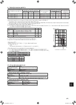
Page 21: ...схему Устройство защитного отключения следует использовать совместно с вводным автоматическим выключателем или автоматическим выключателем проводки 2 В качестве значения F0 следует использовать большее из значений F1 или F2 F1 максимальный общий рабочий ток внутренних приборов 1 2 F2 V1 количество внутренних приборов типа 1 C V1 количество внутренних приборов типа 2 C V1 количество внутренних приб...

Page 22: ...ов от 1 до 9 и свыше 10 и установка номеров ветвей 1 Установка адресов Пример Для установки адреса 3 оставьте переключатель SW12 для адресов свыше 10 в положении 0 и переведите переключатель SW11 для адресов от 1 до 9 в положение 3 2 Установка номеров ответвлений с помощью переключателя SW14 только для серии R2 Определите номер соединения на BC контроллере для трубопровода хладагента внутреннего б...

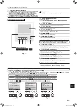
Page 23: ...р вниз 8 Функциональная кнопка F2 Главное окно нажмите для уменьшения температуры Главное меню нажмите чтобы переместить курсор верх 9 Функциональная кнопка F3 Главное окно нажмите чтобы увеличить температуру Главное меню нажмите для перехода к предыдущей странице 0 Функциональная кнопка F4 Главное окно нажмите чтобы изменить скорость вентилятора Главное меню нажмите для перехода к следующей стран...

Page 24: ...eat Нагревание Fig 7 5 Режим охлаждения проверьте выход охлажденного воздуха Режим нагревания проверьте выход нагретого воздуха Проверка работы вентилятора наружного блока 2 Нажмите кнопку и откройте окно настройки режима работы заслонки Проверка работы заслонки в автоматическом режиме 1 С помощью кнопок F1 F2 проверьте работу заслонки в автоматическом режиме Fig 7 6 2 Нажмите кнопку для возврата ...

Page 25: ...dan bir engel ortaya çıkarabilir Cihaz mutlaka ulusal kablo bağlantı yönetmeliklerine uygun şekilde monte edilmelidir Elektrik kablosu hasar görmüşse olası tehlikelerin önlenmesi için mutlaka üretici yetkili servis veya benzeri yetkili kişi veya kuruluşlar tarafından değiştirilmelidir Dikkat R410A soğutucu kullanıldığında mevcut soğutucu borularını kullanmayın R410A soğutucu kullanıldığında geçme ...

Page 26: ...k duvarda boru tesisatı yönünde soldaki şemada gösterilen konumda 75 80 mm çapında bir delik açınız Duvardaki delik dış taraftaki ağız iç taraftaki ağızdan daha aşağı seviyede olacak şekilde meyilli olmalıdır Deliğe yerel piyasadan temin edilen 75 mm çapında bir manşon sokunuz Not Duvara açılan deliğin meyilli olmasının nedeni drenaj akışı sağlamaktır Fig 3 4 A C D E B A Manşon B Delik C İç taraf ...

Page 27: ...nın ayarlanması gerekebilir Duvar içine gömülü soğutucu borusunun uzunluğunu ayarlarken montaj levhasındaki işaretleri referans olarak kullanın Tesisatı yaparken duvardan çıkan boruların uzunluğunda bir miktar tolerans bırakın A Montaj levhası 1 B Geçme bağlantı için referans işareti C Boru deliği D Bağlantı boruları 3 4 İç ünitenin hazırlanması Hazırlık çalışmaları boru tesisatının çıkış yönüne b...

Page 28: ...te C Kanca D kare delik Sol ve sol arka boru tesisatı Fig 3 12 3 Drenaj hortumunu duvar giriş deliğine giriş manşonuna sokarken iç ünitenin üst kısmını montaj levhasına 1 asın Nakliye kutusunun bir parçasını kesin ve şemada gösterildiği gibi silindir olacak şekilde sarın Bu kısmı arka yüzeye bir aralayıcı olarak takın ve iç üniteyi yukarı kaldırın 4 Soğutucu borusunu montaj tarafı soğutucu borusun...

Page 29: ...orular kullanıldığında sıvı ve gaz borularını piyasada satılan yalıtım malzemeleriyle sarın en az 100 C sıcaklığa dayanıklı olmalı veya en az 12 mm kalınlığında olmalıdır Geçme somunu sıkmadan önce boru ve conta bağlantı yüzeylerine ince bir tabaka halinde soğutucu yağı uygulayınız Boru bağlantılarını iki somun anahtarıyla sıkınız Soğutucu boru yalıtımında yalnızca iç ünite bağlantılarının yalıtım...

Page 30: ...tutup kendinize doğru b çekerek drenaj hortumunu çıkarın 3 Drenaj kapağını takın Borunun ucundaki deliğe bir tornavida vb sokarak drenaj kapağının dibine kadar ittirmeye dikkat edin 4 Drenaj hortumunu takın Drenaj hortumunu drenaj kutusu bağlantısının çıkışının dibine erişinceye kadar itin Drenaj hortumu kancasının drenaj kutusu bağlantısının dışarı taşan çıkışına gerektiği gibi tutturulmasına dik...

Page 31: ...etirin 4 Elektrik aksam kutusunun dibindeki kelepçelerle tellerden her birini tutturun A Elektrik kutusu kapağı B Sabitleme vidası C Kelepçe D Toprak kablosu bağlantı kısmı E MA uzaktan kumanda terminal bloku 1 ve 2 de polarite yoktur F İletim terminal bloku M1 M2 S de polarite yoktur G Güç beslemesi terminal bloku L N H Terminal vidası I Toprak kablosu bağlantı kısmı Toprak kablosunu şekilde göst...

Page 32: ...n verilen maksimum sistem empedansını uygulayın 1 Topraklama devresi kesici inverter devresini desteklemelidir Topraklama devresi kesici lokal anahtar veya kablo şalterini birlikte kullanmalıdır 2 F1 veya F2 den büyük olanı F0 değeri olarak kabul edin F1 İç ünitelerin toplam maksimum çalışma akımı 1 2 F2 V1 Tip1Miktarı C V1 Tip2Miktarı C V1 Tip3Miktarı C V1 Diğerlerinin Miktarı C İç ünite V1 V2 Ti...

Page 33: ...asındaki ve 10 un üzerindeki adreslerin düzenlenmesi ve şube numaralarının düzenlenmesi 1 Adres ayarının yapılması Örnek Adres 3 ise SW12 yi 10 ve üzeri için 0 da tutun ve SW11 i 1 9 için 3 e getirin 2 Bölüm numarası ayarının yapılması SW14 sadece R2 serisi İç ünite soğutucu borusunu BC denetleyicinin uç bağlantı numarası ile eşleştirin R2 serisi dışında 0 olarak bırakın Tüm döner anahtarların fab...

Page 34: ...elektrik ve kontrol kablolarında gevşeme hatalı polarite ve fazlardan birinde kopma olup olmadığına bakınız 500 Voltluk bir megommetreyle besleme kaynağı terminalleriyle toprak arasında en az 1 0 MΩ direnç bulunduğunu kontrol ediniz Bu testi kontrol kablosu düşük gerilim devresi terminallerinde yapmayınız Kumanda arayüzü 7 Çalışma testi 4 3 2 1 5 6 7 8 9 0 Fig 7 1 İşlev düğmeleri Adım 1 Uzaktan ku...

Page 35: ...rol edin Isıtma modu Sıcak hava üflemesini kontrol edin Dış ünite fanının çalışmasını kontrol edin 2 Kanatçık ayar ekranını açmak için düğmesine basın OTOMATİK kanatçık kontrolü 1 F1 F2 düğmeleri ile otomatik kanatçığı kontrol edin Fig 7 6 2 düğmesine basarak Test run Test çalıştırma işlem ekranına dönün 3 düğmesine basın F1 F2 F3 F4 Cool Pipe Auto Switch disp Mode Fan Remain Test run F1 F2 F3 F4 ...

Page 36: ...Не забудьте указать контактный адрес номер телефона в данном руководстве прежде чем передать его клиенту Lütfen bu kılavuzu müşteriye teslim etmeden önce iletişim adresini telefon numarasını eklemeyi unutmayın HEAD OFFICE TOKYO BUILDING 2 7 3 MARUNOUCHI CHIYODA KU TOKYO 100 8310 JAPAN Название Компании ООО Мицубиси Электрик РУС Адрес 115114 Российская Федерация г Москва ул Летниковская д 2 стр 1 5...

Reviews: