Mitsubishi Electric AT-50B Installation Manual Download Page 12

– 12 –

2-3. Initial Settings

(1) Initial startup settings:

Before turning on the controller, first make sure that the controller, indoor units, and outdoor units have been installed properly 
according to the instructions detailed in the respective manuals. 
Turn on the controller and the units.
• This manual is intended for the first startup after the unit has been shipped from the factory. If the setting has been changed even 

once, the popup window or setting screens explained below may not appear. In this case, see section “Usage - Main Menu 
Settings” in the Instruction Book.

• AT-50B can be used as a Main controller or a Sub controller. At the time of factory shipment, AT-50B is set as a Main controller. The 

MAIN/SUB setting can be changed on the Initial Settings 1/Basic System screen from the Service Menu. (Refer to section 2-3(2)-1 
for details.)

• Change the MAIN/SUB setting before making other initial settings, otherwise some saved information will be lost upon restart after 

the setting is changed.

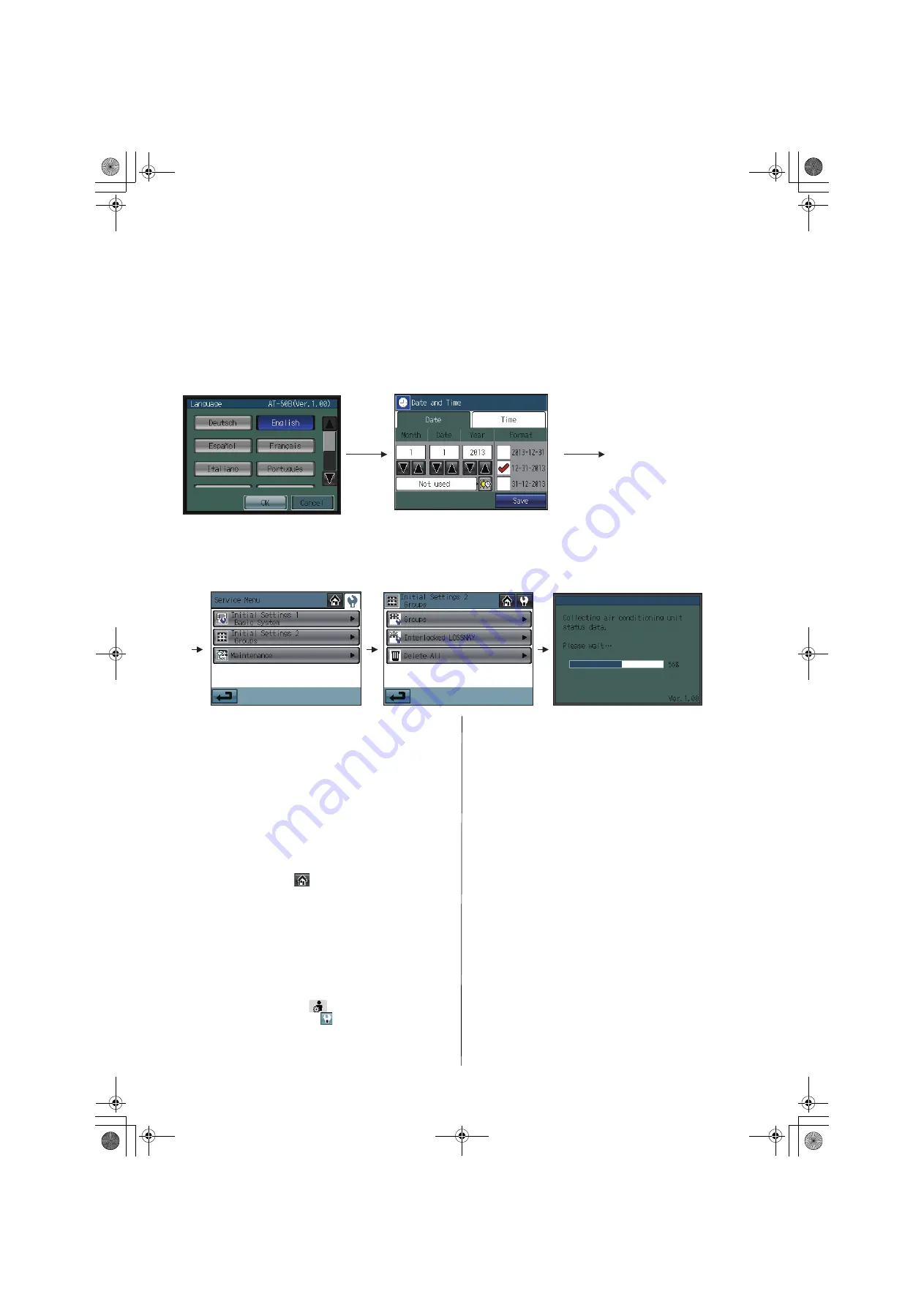
<When a popup message “Make a setting from Initial Settings 
1.” appears>

(c) Press the OK button to close the popup window and display 

the Service Menu screen.

(d) Touch the Initial Settings 1/Basic System button to make a 

setting. (Refer to section 2-3(2)-1 for details about Basic 
controller settings.)
Save the settings, and go back to the Service Menu.

(e) Touch the Initial Settings 2/Groups button to make a setting. 

(Refer to section 2-3(2)-2 for details about group settings, 
2-3(2)-3 for details about Interlocked settings.)
Save the settings, and go back to the Service Menu.

(f) Touch the HOME button [

] to bring up a popup 

confirmation screen. 
Press the OK button to begin the communication.

(g) The message (shown above) will appear on the screen, 

displaying the initialization progress. When initialization is 
complete, the screen will automatically return to the HOME 
screen. 
(Initialization will take up to five minutes.) 
* To change settings later, perform a test run, or verify the 

maintenance information.

1

Touch Main Menu button [

] on the HOME screen. 

2

Touch Service Menu button [

] on the Main Menu screen.

3

Enter the password to log on to the Service Menu screen. 
(Refer to section 2-3, 2-4, and 2-5.)

<When a popup message “Make a group setting using the 
Main controller. When the group setting has been made, reset 
the power to the Main controller.” appears>

(c) While the popup message is displayed, the unit communicates 

with the main controller. The popup window will close when the 
communication is completed.
* To change the settings, press the Cancel button while the 

popup window is displayed. The Initial Settings 1/Basic 
System screen will appear. If Basic controller settings are not 
made yet, change the settings.

(d) The message (shown above) will appear on the screen, 

displaying the initialization progress. When initialization is 
complete, the screen will automatically return to the HOME 
screen.
(Initialization will take up to ten minutes.) 
* The group name needs to be set on the sub controller after 

normal startup, as it cannot be sent from the main controller. 
Refer to the Instruction Book for details.

(a) The Language screen will appear.

1

Touch the button to select the 
display language of your choice. 

2

Touch the OK button. 

(b) The Date and Time screen will appear. 

1

Set the current date on the Date tab, and set the current time on the Time tab, 
using the 

 and 

 buttons to change the values.

2

Check the checkbox next to the date/time format of your choice. 

3

Touch the Save button to save the settings.

WT06990X04_GB.book  12 ページ  2018年5月22日 火曜日 午後1時55分

Summary of Contents for AT-50B

Page 1: ...ts with wet hands To reduce the risk of injury or electric shock before spraying a chemical around the controller stop the operation and cover the controller To reduce the risk of injury or electric shock stop the operation and switch off the power supply before cleaning maintaining or inspecting the controller Properly install all required covers to keep moisture and dust out of the controller Du...

Page 2: ...cables and cable access holes with putty The controller should be repaired or moved only by qualified personnel Do not disassemble or modify the controller Improper installation or repair may cause injury electric shock or fire To reduce the risk of shorting electric shock fire or malfunction do not touch the circuit board with tools or with your hands and do not allow dust to accumulate on the ci...

Page 3: ...ual 1 2 Mounting bracket 1 AT 50B Power lamp Display screen Touch panel For connection to the M NET A B Terminal for connection to the M NET transmission cable non polarized External output adapter cable access hole External input adapter cable access hole Controller cover mounting screw SD memory slot for program updates TB7 TB3 ME MA MA R2 TB7 TB3 MA MA 051 001 106 006 007 008 009 010 056 057 00...

Page 4: ... as for the indoor units apply An M NET interface sold separately is required 1 50 M NET remote controller Assign an address that equals the address of the main indoor unit with the lowest address in the group plus 100 Add 150 instead of 100 to set a sub remote controller 101 200 Sub system controller Assign an address that equals the lowest number of the group to be controlled plus 200 201 250 DI...

Page 5: ... the controller Have extra cables to extend these cables as necessary To install the controller according to the instructions provided in sections a and b 1 above Include an extra 30 cm 12 in of cable to provide adequate slack in the cable Remove the sheath on the M NET transmission cable up to 20 cm 8 in from the end To install the controller according to the instructions provided in section b 2 ...

Page 6: ...transmission cable is non polarized Insert the cables in the groove on the controller so they will not be pinched when the cover is installed To route the cable along the wall surface Secure the cables in place with a cable cover and seal the gap between the cable cover and the controller with putty 5 Replace the cover Snap the cover into place and attach it to the controller with a screw at the b...

Page 7: ...set to a value between 0 2 and 1 seconds Mode External input setting Notes 1 Not used Factory setting Select this mode when not using an external signal input function 2 Emergency Stop Level signal Using a level signal all the air conditioning units will be stopped collectively in an emergency During an emergency stop the ON OFF operation from the local remote controllers will be prohibited and th...

Page 8: ... extension cables are field supplied Note External output of the AT 50B is a dry contact Select an external power supply suitable for the relays used 12 VDC or 24 VDC To prevent malfunction connect the external power supply to the input circuit with the correct polarity CN2 X1 AT 50B X1 1 2 3 4 5 Maximum 10 m 32 ft Field supplied Yellow Green ON OFF or Emergency stop X1 X2 Y1 Y2 CN2 X1 AT 50B X2 Y...

Page 9: ...B and 2GB SD memory cards by SanDisk are supported Parts Model Usage Note External input output adapter PAC YT51HAA Enables the use of external input output function Required to use the external input output function 5 wire cable input 4 wire cable output SD Logo is a trademark of SD 3C LLC a b c a Remove the SD memory card slot cover from the controller b Insert the SD memory card into the slot u...

Page 10: ... only or both remote controllers and sub system controllers Access to ON OFF Mode Set Temp Filter Reset Air Direction Fan Speed Timer and Check Water sign Air To Water PWFY 13 External input mode Selects the external input mode 13 Filter sign Displays or suppresses the filter sign on the HOME screen 13 Dry mode Includes or excludes Dry mode as an option for the operation mode 13 Operation mode con...

Page 11: ...GRID zoom out view GRID zoom in view LIST view GROUP view Main Menu screen Login Page screen 1 Password Change screen Service Menu Service Menu screen Initial Settings 1 Basic System Initial Settings 2 Groups Groups Interlocked LOSSNAY Delete All System View Malfunction Log Gas Amount Check Maintenance Test Run Software update Button name Main Menu Service Menu Password Change Return HOME Cancel L...

Page 12: ... communication g The message shown above will appear on the screen displaying the initialization progress When initialization is complete the screen will automatically return to the HOME screen Initialization will take up to five minutes To change settings later perform a test run or verify the maintenance information 1 Touch Main Menu button on the HOME screen 2 Touch Service Menu button on the M...

Page 13: ...ohibition Setting on the AT 50B The factory setting is Enabled Remote controller access setting 1 Touch the button labeled 4 in the figure to switch between SC RC and RC Only Select SC RC to prohibit access from both the system controllers and remote controllers and select RC Only to prohibit access from only the remote controllers The factory setting is RC Only Access to ON OFF Mode Set Temp Filt...

Page 14: ...ing functions Saving the settings 1 Touch the Save button to save the settings 2 2 Group settings This setting can be made only when AT 50B is set as a main controller If AT 50B is set as a sub controller the setting can be monitored only Enter the group settings on the Groups screen air conditioning units general equipment and their respective group names that are connected to AT 50B Touch Initia...

Page 15: ...n be assigned to each group Do not assign a system controller that does not support Air To Water PWFY to Air To Water PWFY group which may result in unit malfunction 5 After all the settings have been made touch the Save button Group settings for general equipment 1 Touch the model selection button labeled 2 in the figure to access the Model selection screen Touch the model selection button labele...

Page 16: ...ked indoor unit button labeled 2 in the figure On the popup window that appears check the address of the indoor units to be interlocked with the ventilation units Up to 16 indoor units can be assigned to each ventilation unit 3 After all interlocked operation settings have been made touch the Save button 2 4 Batch deletion Available only when AT 50B is set as a main controller To delete all group ...

Page 17: ... is Air To Water PWFY group 2 Operation mode Touch this button to switch the operation mode 3 Pipe temperature 1 The pipe temperature of the unit with the lowest address in a given group will appear 4 Advanced settings Touch this button for advanced settings 1 The water temperature will appear if the group is Air To Water PWFY group The water temperature to be displayed depends on which temperatur...

Page 18: ...utes to 1 hour and check results will be displayed upon completion When the amount of refrigerant charge is normal Normal will appear on the screen and if the outdoor units are low on refrigerant due to leaks Lo will appear It is not necessary to keep this page open until checking is completed Even if the screen is closed the check results and the log will be displayed next time this page is opene...

Page 19: ...he popup message to begin the update process 6 The lit LEDs on the three buttons F1 F2 and Collective ON OFF will indicate a successful completion of the update While update is in progress the LEDs on the F1 and F2 buttons will alternately blink Consult your dealer if the update is not completed in 10 minutes 7 After the update has been completed turn the DIP switch 4 to OFF to restart the AT 50B ...

Page 20: ...ions Electromagnetic Compatibility Directive 2014 30 EU Restriction of Hazardous Substances 2011 65 EU HEAD OFFICE TOKYO BLDG 2 7 3 MARUNOUCHI CHIYODA KU TOKYO 100 8310 JAPAN MANUFACTURER MITSUBISHI ELECTRIC CORPORATION Air conditioning Refrigeration Systems Works 5 66 Tebira 6 Chome Wakayama city 640 8686 Japan WT06990X04_GB book 20 ページ 2018年5月22日 火曜日 午後1時55分 ...

Reviews: