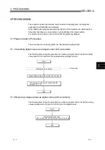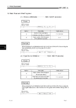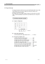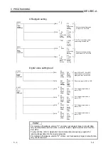
App - 4 App - 4
MELSEC-A
APPENDIX
Appendix 3 Precautions For Reading A Digital Output Value
(For Hardware Version "C" or Earlier)
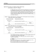
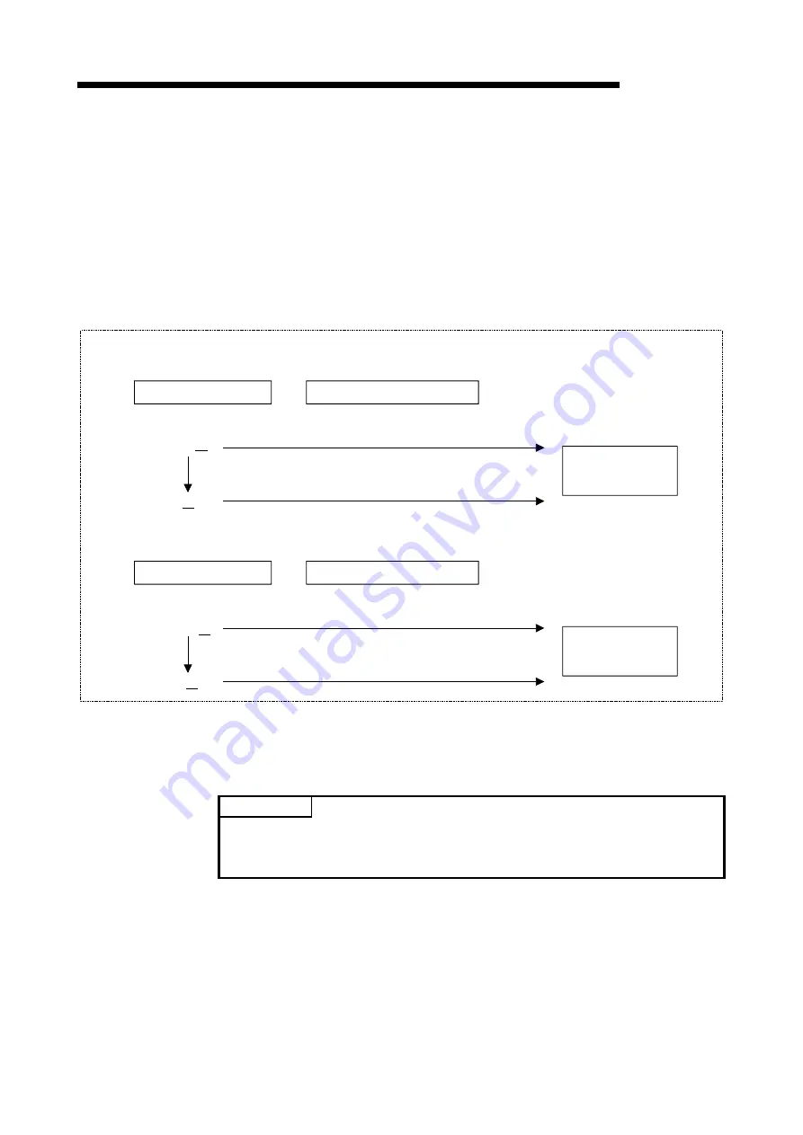
If a digital output value is read from the PLC CPU during A/D conversion processing of
the A1S66ADA (For Hardware Version "C" or Earlier), data may be read to the lower
order byte (Xn0 to Xn7) and higher order byte (Xn8 to XnB) at different timings.
In this case, old A/D conversion data are stored into the lower order byte, and new A/D
conversion data into the higher order byte as the read data from the PLC CPU,
resulting in data mismatch. (When a carry or borrow occurs, a difference of 256 occurs
in the digital output value.)
A/D conversion processing
Read processing from PLC CPU
Read data
511(01FF
H
)
255(00FF
H
)
Digital output value
A/D conversion processing
Read processing from PLC CPU
Read data
0(0000
H
)
256(0100
H
)
Digital output value
256(0100
H
)
255(00FF
H
)
Lower order byte (Xn0 to Xn7) read (FFH)
Higher order byte (Xn8 to XnB) read (01H)
Lower order byte (Xn0 to Xn7) read (00H)
Higher order byte (Xn8 to XnB) read (00H)
Example 1) When a digital output value is read from the PLC CPU during A/D conversion processing
(during carry occurrence) of the A1S66ADA
Example 2) When a digital output value is read from the PLC CPU during A/D conversion processing
(during borrow occurrence) of the A1S66ADA
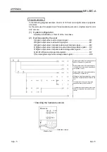
The read digital output value is compared every scan with the digital output value read
at the previous scan to update only normal data.
An example of a program to read a digital output value converted from analog on
Channel 3 is shown below.
POINT
Since data inconsistency does not occur in modules of hardware version "D" or
later, measures for updating only normal data are not needed.
For checking the hardware version, refer to the next page.
Summary of Contents for A1S66ADA
Page 2: ......
Page 13: ...2 2 2 2 MELSEC A 2 SYSTEM CONFIGURATION 2 MEMO ...
Page 44: ...6 2 6 2 MELSEC A 6 TROUBLESHOOTING 6 MEMO ...
Page 51: ......


