LIGHTING SYSTEM Troubleshooting
TURN-SIGNAL LIGHT AND HAZARD LIGHT CIRCUIT
OPERATION
<Turn-signal lights>
When operation is normal
When the ignition switch is switched to the
“ON” position, battery voltage is applied (via the
hazard-flasher switch) to the turn-signal and
hazard-flasher unit.
When the turn-signal switch is switched to the
“LH” (or
position, Trl (within the flasher
unit) is switched ON and the relay contact (also
within the flasher unit) is switched ON. As a
result, the “LH” (or
turn-signal lights and
turn-signal indicator light illuminate.
At the same time, charging to the capacitor (via
begins, and charging continues until the
lower-limit potential (set by
is reached.
When the capacitor becomes fully charged, the
output reverses and Trl is switched
OFF; the relay contact is also switched OFF,
and, as a result, the “LH” (or
turn-signal
lights and turn-signal indicator light are switched
OFF.
At the same time that Trl is switched OFF, the
capacitor begins discharging, and, when dis-
charging finishes, the output of
once
again reverses and Trl is switched ON, after
which the “LH” (or
turn-signal lights and
turn-signal indicator light illuminate.
As a result of the continued repetition of the
steps described above, the “LH” (or
turn-signal lights and turn-signal indicator light
flash ON and OFF repeatedly.
If one light’s wiring is damaged or disconnected
If the bulb for one turn-signal light is damaged on
disconnected, the result is an overall increase of
the resistance for the entire light circuitry,
resulting is a decrease of the voltage at the
part within the flasher unit.
As a result of this being detected, the lower-limit
potential set by
is increased, with the
result that the time required for charging of the
capacitor becomes shorter.
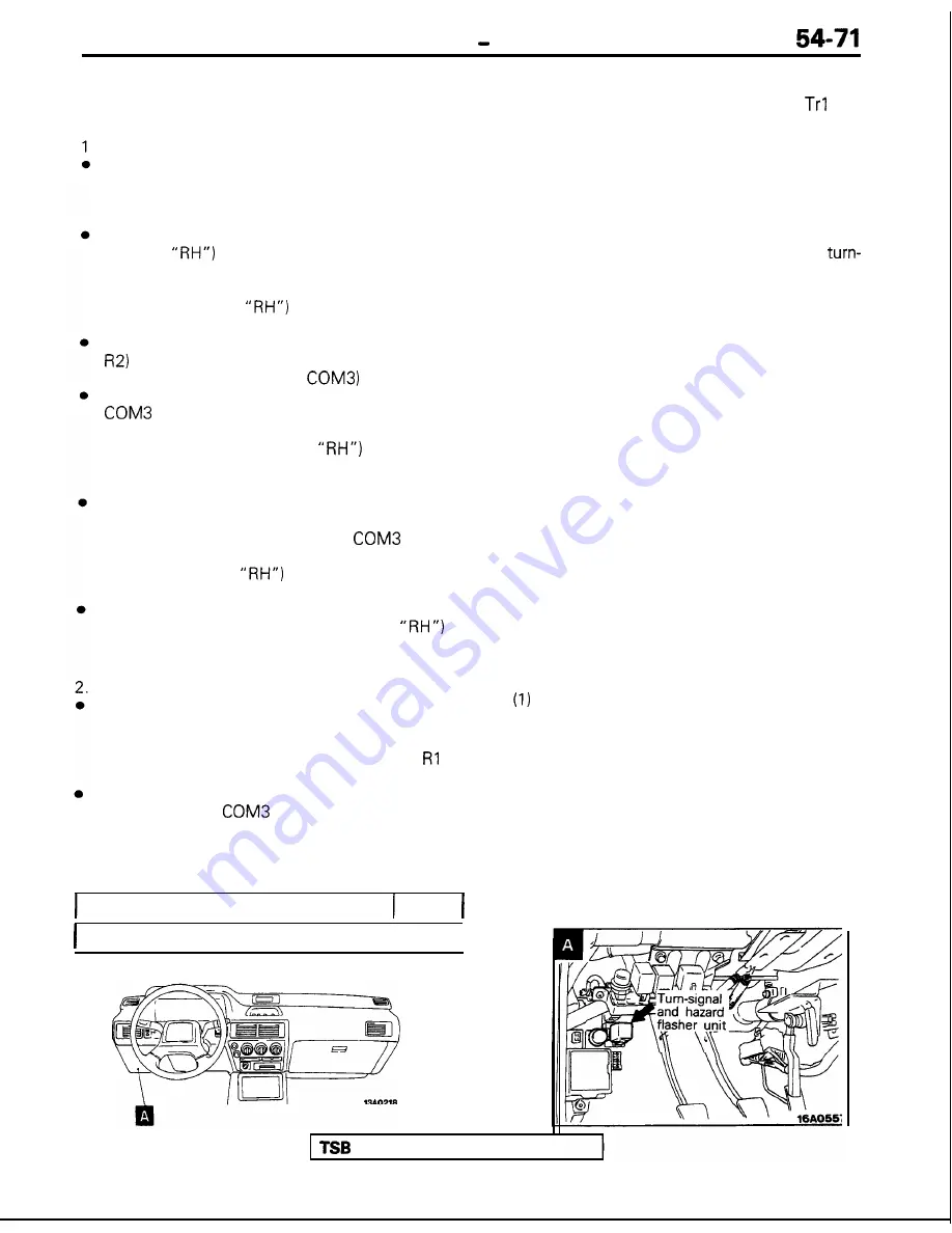
COMPONENT LOCATION
Name
Symbol
Turn signal and hazard flasher unit
I
A
I
l
As a result, the ON and OFF cycles of
also
become shorter, and thus the number of flashes
of the lights becomes greater.
<Hazard-warning lights>
l
When the hazard-warning switch is switched to
the “ON” position, the relay contact of the
flasher unit is switched ON and OFF repeatedly,
in the same manner as for the operation of the
turn-signal lights, and the left and right
signal lights and turn-signal indicator lights
simultaneously flash repeatedly.
NOTE
l
The number of flashes of the hazard-warning
lights does not change if there is damaged or
disconnected wiring of one light.
TROUBLESHOOTING HINTS
1. The turn-signal lights and hazard-warning lights
do not operate at all.
l
Check the hazard-warning switch con-
tact (power supply side).
l
Check the flasher unit.
2. All turn-signal lights at the left (or right) side do
not function.
(1) The hazard-warning lights function normally.
l
Check the hazard-warning switch con-
tact (turn-signal side).
l
Check the turn-signal switch.
3.
The number of flashes of the turn-signal lights is
excessive.
l
Check the bulbs.
4. The hazard-warning lights do not function.
The turn-signal lights function normally.
l
Check the hazard-warning switch con-
tact (hazard-warning light side).
Revision


