21/1531-ASP11301 Uen B3 2016-02-17
44
A
LARMS
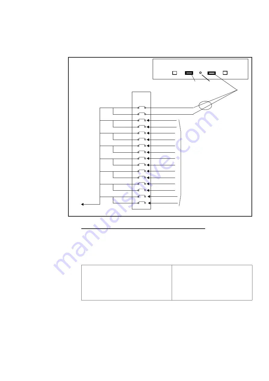
Connect the ALU2 board to the MDF according to the cabling list for the site. Use cable
TSR 491 0306 or similar. For an example of connection to the ALU2 board, see Figure
35: MDF Alarms for the Fan Unit BFD 509 08/4 on page 44
Figure 35: MDF Alarms for the Fan Unit BFD 509 08/4
The Fan unit BFD 509 08/4 has the following alarm indicators:
•
Yellow LED
The yellow LED is blinking when the Alarm is activated. The Alarm can be acti-
vated either by heat or lost of one of the -48V feeding.
Table 16 Fan Unit Alarms
5.2
MIVOICE MX-ONE LITE, 3U UNIT, EXTERNAL ALARM
The
Alarm Input
, which is located on the rear side of the unit, has two pins, 1 and 3,
which can be detected as alarms when either of them is closed to ground. To reach the
MDF
a
b
a
b
a
b
a
b
a
b
a
b
a
b
a
b
ALU2
2 x TSR 491 0306/20M
inputs
FAN unit BFD 509 08/4
Violet FAN alarm
Turquoise GND
TSR9020274/2200
SXK1062097/1
LED
Fan alarm_A is active when one or more of
the conditions is/are:
-48Va or -48Vb input is too low (towards 0
V)
or
the temperature is above 55 degrees C
or
the temp.sensor fails (out of range)
or
the FAN motor current is out of range
or
the FAN or motor voltage regulation fail


