For more details, see LT-996 and LT-969 on the Mircom website and the USB fl ash.
Mircom technical support: 1-888-647-2665
ASSEMBLING TX3-TOUCH-F15-B
© Mircom 2015
Printed in Canada
Subject to change without prior notice
LT-6125 rev 0
Warning: Turn the power off
before wiring.
Line 1
Phone Lines
Non-confi gurable PBX
systems are not supported.
For more information,
contact Mircom technical
support at 1- 888-647-2665.
Line 2
(optional)
T R
T
R
8
Postal Lock
Postal Lock
(Input 1)
Fire Alarm Override (Input 2)
Door Contact (Input 3)
22 AWG
Warning: Do not attach
the wiring until after the
postal lock is installed.
Fire
Panel
Door
Contact
TS5
7
Activation of this
input relocks the main
door (Output 1).
Activation of this input
unlocks the main
and auxiliary doors
(Outputs 1 and 2).
Postal Lock:
see
RS-485:
see
Phone Lines:
see
USB connector:
Connect to computer
for fi rmware upgrade
and confi guration
(maximum length of
USB cable:
8 feet/2.4 m)
Guard
Phone board
connector
TX3-MDM
Modem board
connector
P7
P4
8
7
9
TX3-IP Module
Connection
P5
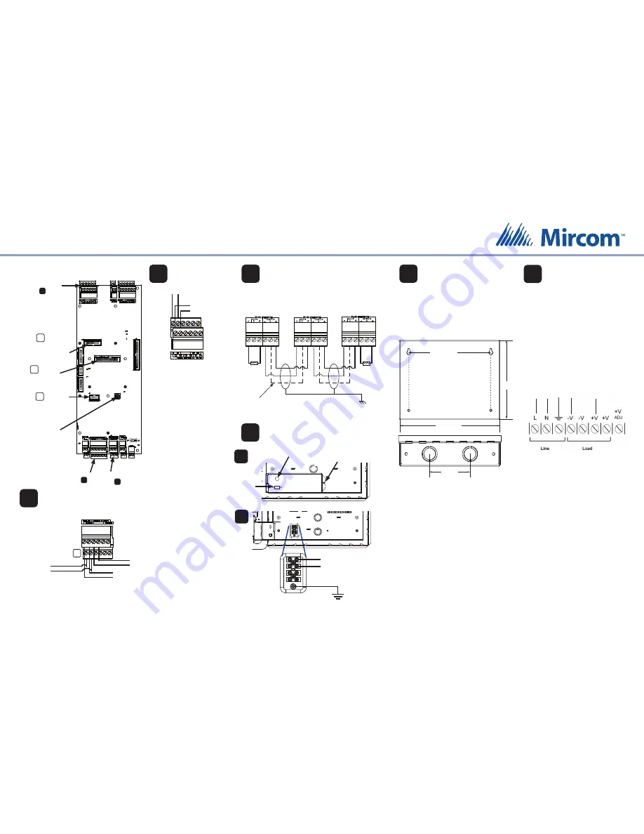
22 AWG twisted pair, maximum length: 4000 ft (1219.2 m)
Mircom recommends shielded cable
RS-485
9
120 Ω
120 Ω
Panel 3
Last
panel on network
Panel 2
Panel 1
First
panel on network
Optional common
reference connection
if available
Connect shield to chassis
ground on one panel only
Ground and Power
10
Remove nut and
open cover to
access ground and
power terminals
To MD-990 24 VDC
power supply
Ground
(16 AWG)
To surface mount the power supply enclosure:
1.
Find a suitable location for the power supply
enclosure, such as over a wall stud.
2.
Using the power supply enclosure as a template,
mark the back mounting hole locations. Ensure
that at least one side is over a wall stud.
3.
Remove the power supply enclosure and place
the top two screws halfway into the marked hole
locations and wall stud.
4.
Place the power supply enclosure onto the two
screws.
5.
Screw the other two screws into the remaining
holes.
6.
Tighten all four screws into place.
Note: The enclosure can also be mounted directly
onto the drywall using anchors.
To building
power
To Touch Screen
{ {
1.
Connect the MD-990 load power supply
wires to the Touch Screen terminal
screws as shown in step 10.
2.
Connect the building power supply
wires to the MD-990 line terminal screws
as shown below.
3.
Connect the other end of the building
power supply wires the line voltage
terminals.
4.
Turn the power on by pressing the
power button.
Mount the MD-990
24 VDC, 156 W
Power Supply
11
12
Connect the Power
Overall dimensions including door:
height: 7 23/32” (196 mm)
width: 9 53/64” (250 mm)
depth: 2 37/64” (66 mm)
Knockout dimensions: 1 1/8” (29 mm) and 7/8” (22 mm)
9 1/5” (241 mm)
7 1/5”
(191 mm)
7 3/4” (197 mm)
3” (76 mm)
A
B
USB port for
keyboard
Power button
Mircom
CANADA - Main Offi
ce
25 Interchange Way
Vaughan, ON L4K 5W3
Tel: (888) 660-4655
(905) 660-4655
Fax: (905) 660-4113
U.S.A
4575 Witmer Industrial Estates
Niagara Falls, NY 14305
Tel: (888) 660-4655
(905) 660-4655
Fax: (905) 660-4113
TECHNICAL SUPPORT
North America
Tel: (888) Mircom5
(888) 647-2665
International Tel:
(905) 647-2665
+
-


