


10
| DVI-Ramp
2
/ DVI-Ramp
2
DSK
2.4 Control Interface
The DVI-Ramp
2
has no local controls beyond the power switch and the Reset pushbutton. All adjustment is
done using a software interface running on a computer connected to one of the three control ports.
Miranda has developed software for this purpose. The software and documentation can be downloaded from
Miranda’s website at www.miranda.com. The software includes Context-Sensitive Help.
Alternatively, users may create their own software. Programming documentation is available on demand.
Note:
Connecting to an RS-232 device or network
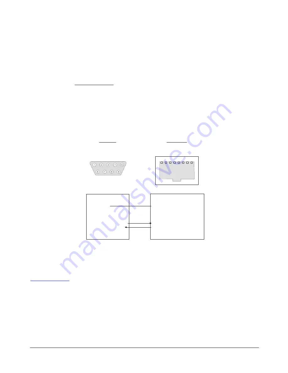
The "RS-232/GPI" RJ45 connector is used to preserve space on a busy panel while
accommodating RS-232 and GPI interfaces. The RS-232 interface specifies a DE-9S connector,
so if you are using this interface you may require a DE-9S-to-RJ45 adapter cable. The pin-out of
the "RS-232/GPI" connector is shown below:
1: GPI-IN2
2: GPI-OUT2
3: GND
(also GPI-OUT2_GND)
4: GPI-OUT1
5: GPI-OUT1_GND
6: GPI-IN1
7: DVI-Ramp2 RS-232_RX
8: DVI-Ramp2 RS-232_TX
DVI-Ramp 2
Computer
RJ-45
DE-9
pin 5: Ground
pin 3: TX out of computer
pin 2: RX into computer
1
8
Figure 2.3
RS-232 / GPI RJ45 connector pin-out
3 Operation
The DVI-Ramp
2
has no local controls beyond the power switch and the reset pushbutton. Operational
concerns are outlined here, but for detailed operating instructions, see the documentation at
www.miranda.com
.
3.1 Powering
Up
The power switch is located on the rear panel of the DVI-Ramp
2
, just above the power connector. Connect
the provided power supply to the power connector and set the switch to ON (I).
3.2 Front Panel Indicators and Controls
There are five Input Status LEDs which are mounted on the front edge of the DVI-Ramp
2
’s circuit board, and
which can be seen through holes in the front panel of the case. The DVI-Ramp
2
DSK model has an extra
LED for the video input status.


