Miranda Densite series DDA-1113 Manual To Installation And Operation Download Page 13

GUIDE TO INSTALLATION AND OPERATION 

DDA-1113  |  

13


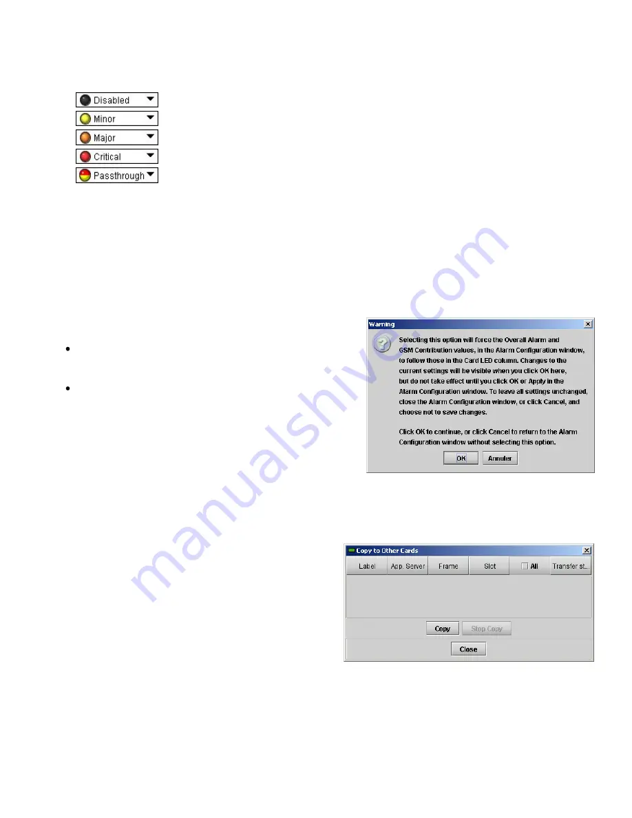
Levels associated with these alarms: t

he pull-down lists may contain some or all of the following options: 


The alarm makes no contribution (black icon) 


The alarm is of minor importance (yellow icon) 


The alarm is of major importance (orange icon) 


The alarm is of critical importance (red icon) 


The alarm exists but has no effect (used for text and composite alarms)


Shortcut:  

if you click in one of the Set all command under each major heading in the Status/Name line, you will 

open a pull-down that lets you assign a level to all alarms in that column simultaneously. 

 
Log Events 

iControl maintains a log of alarm events associated with the card. The log is useful for troubleshooting and identifying 
event sequences. Click in the checkbox to enable logging of alarm events for each individual alarm. 

At the bottom of the window are several other controls: 

 
Overall alarm and GSM contribution follow card LED 

Click in the checkbox to force the Overall alarm and GSM 
contribution to be identical to the Card LED status 


All Overall alarms and GSM contributions for which there is 

a Card LED alarm will be forced to match the Card LED 
alarm 


All Overall Alarms and GSM contributions for which there is 

no Card LED alarm will be forced to Disabled 


A warning box will open allowing you to confirm the action, 
since it will result in changes to the configuration and there is 
no 

undo

 function. 


Copy to other cards 

Click this button to open a panel that allows the alarm 
configuration set for this card to be copied into another DDA-
1113 card. 
Select one or more destination cards from the list in the 
window by clicking in check boxes, or all of them by clicking 
in the 

All 

checkbox. 


Figure 3.5 

Overall Follow Card Led - Warning Box 

Figure 3.6 

Copy to Other Cards 

Summary of Contents for Densite series DDA-1113

Page 1: ......

Page 2: ...quipment has been tested and found to comply with the requirements of the EMC directive 2004 108 CE EN 55022 Class A radiated and conducted emissions EN 55024 Immunity of Information Technology Equipm...

Page 3: ...6 2 Installation 7 2 1 Unpacking 7 2 2 Installation in the Densit frame 7 2 3 Rear Connector Panel 7 3 Operation 8 3 1 Card Edge Controls and Indicators Status Led 8 3 2 Local control using the Densi...

Page 4: ...GUIDE TO INSTALLATION AND OPERATION DDA 1113...

Page 5: ...he content of the audio signal A multi colored LED visible with the door closed reports the card status The DDA 1113 requires a single or a double rear connector panel 1 2 Features Digital audio distr...

Page 6: ...terface The front card edge of the DDA 1113 incorporates two elements Status LED see section 3 1 Select Button see section 3 2 Figure 1 2 Card edge controls and indicators SDA 1101 SD DIGITAL VIDEO DI...

Page 7: ...st be mounted in a DENSIT 2 or DENSIT 3 frame It is not necessary to switch off the frame s power when installing or removing the card See the DENSIT Frame manual for detailed instructions for install...

Page 8: ...dition cannot cause the LED to assume that status If more than one LED status is possible for a particular error condition the status is configurable See Section 3 2 2 for details The factory default...

Page 9: ...pushbuttons located beneath the display The functionality of the pushbuttons is as follows Used for menu navigation and value modification SELECT Gives access to the next menu level When a parameter v...

Page 10: ...to a correct input status LENGTH This command allows a manual adjustment of the correction applied to the input signal The input status is displayed at the same time to ease the setting o Set the inpu...

Page 11: ...t of factory selected values that can be used to return your DDA 1113 to a standard operating condition The default values are shown as underlined in the DDA 1113 Menu on page 10 3 3 1 Status Tab This...

Page 12: ...f selected individual alarms to the status LED located on the front card edge The Card LED status is shown at the bottom of the alarm tree in the Status Name column Overall Alarm This column allows co...

Page 13: ...of alarm events for each individual alarm At the bottom of the window are several other controls Overall alarm and GSM contribution follow card LED Click in the checkbox to force the Overall alarm and...

Page 14: ...A 1113 The boxes titled Label Short Label Source ID and Comments are editable the user can enter their own information The Advanced button displays the name of the server within the iControl system th...

Page 15: ...tputs Signal AES3 id SMPTE 276M Level 1 Vpp Impedance 75 unbalanced Rise fall time 36 32 ns Overshoot 0 Return loss 15 dB 6 144MHz Jitter reduction 6 dB 20 kHz Specific jitter 0 005 UI pp 700 Hz to 10...

Reviews: