


Guide to Installation and Operation
2
|
ADC-191p
2.0 Physical Layout
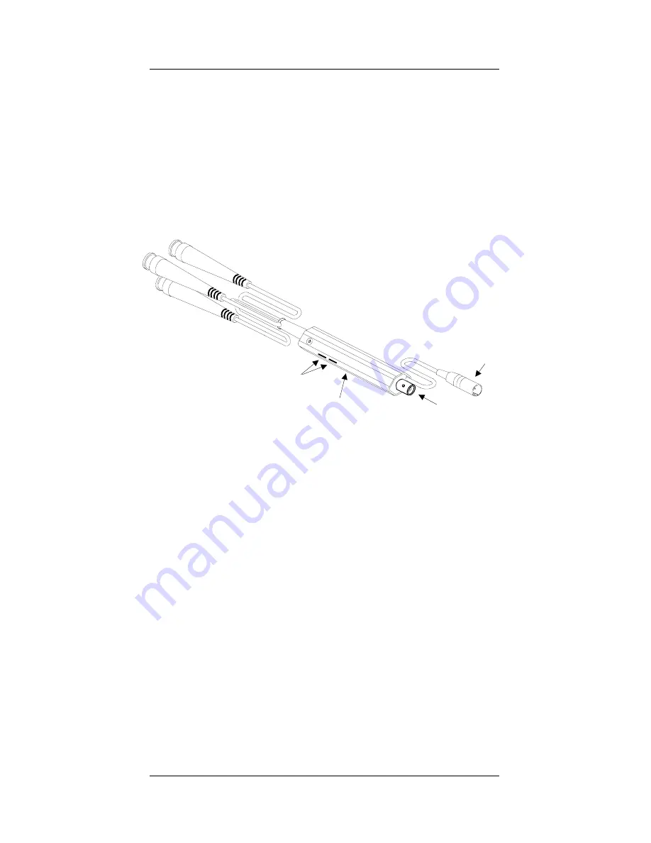
Figure 2 illustrates the ADC-191p’s major parts and their
locations. SMPTE/EBU or Betacam sources are
connected to the CAV input BNCs and the 4:2:2 serial
digital output is provided by the 4:2:2 output BNC. Error
status is provided by the status LED and mode settings
are configured by two 3-position slide switches. Finally,
the power source is connected to the power connector.
.
Figure 2:
Physical layout of the ADC-191p
4:2:2 output
Power connector
CAV inputs
Status LED
3-position slide switches


