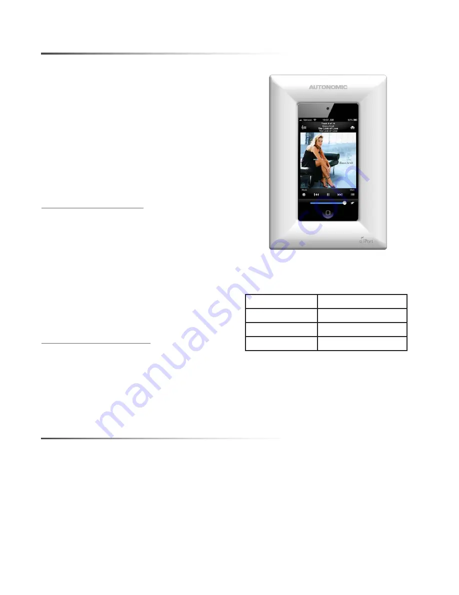
Mirage KP-iOS User Manual Download Page 2

KP-iOS

2

INTRODUCTION

The 

Mirage

 KP-iOS is an in-wall system that 

allows iPod touch

®

 (4th generation) to become a 

semi-permanent fixture in your wall. The system 
allows you to use an iPod touch as a key panel 
to control your Mirage Audio System via the 
Mirage App and wireless communication. Before 
installing and using the 

Mirage 

KP-iOS, please 

read and follow all of the instructions in this 
manual carefully. 

System Capabilities:

* Charges iPod touch while it is mounted

via Cat5 cable connected to an Autonomic

Mirage Amplifier.

* Mounts iPod touch in-wall.
* Provides additional long distance power only

up to 200’ using 18 awg wire if required. 

* See chart for additional wiring specs.

KP-iOS Box Contents

1. Mounting System

(bezel, retainer, mounting frame) 

1. Electronics:  30-pin Connector Board

1. Cut-Out Template

1. Instruction Manual

ReqUIReD TOOls 

* #2 Phillips screwdriver
*  Wire cutters and wire strippers
* RJ-45 cable crimp tool and modular

connectors

* Sheet rock saw

(for retrofitting into an existing wall)

Wire Gauge

Distance (Feet)

22awg

75

20awg

120

18awg

200

Summary of Contents for KP-iOS

Page 1: ...In Wall Control Mount for iPod Touch...

Page 2: ...ties Charges iPod touch while it is mounted via Cat5 cable connected to an Autonomic Mirage Amplifier Mounts iPod touch in wall Provides additional long distance power only up to 200 using 18 awg wire...

Page 3: ...nds To prepare the Cat5 cable and RJ 45 connector for KP iOS installation 1 Pull the Cat5 wire through the wall between the desired locations 2 Use a stripper or knife to strip about 1 of the cable ja...

Page 4: ...of seconds 1 Determine the location for the KP iOS and the wall plate 2 Perform an obstruction survey to ensure there are no studs conduit pipes heating ducts or air returns that will interfere with t...

Page 5: ...KP iOS 5 Figure 3 KP iOS System Connection M 800 MIRAGE 8 ROOM DIGITAL AMPLIFIER Keypad Ports 2 1 3 4 POWER INTERNET WIRELESS ETHERNET PORT...

Page 6: ...the removal of the toggle caps 7 Hand tighten the four Roto Lock screws on the KP iOS mounting frame as shown in Figure 5 The Roto Lock clamps will automatically rotate into position behind the wall a...

Page 7: ...lign power button on iPod with Power Button on bezel See Figure 6 10 Place back plate over iPod and secure with 4 screws The retainer has a foam pad to hold the iPod touch very securly See Figure 7 11...

Page 8: ...e mounting frame as shown in Figure 9 Note To sync your iPod touch with your computer please follow the steps above in reverse order to remove the iPod touch and sync Once your synchronization is comp...

Page 9: ...uch is now fully functional Use the iPod touch screen to choose home screen applications music email A power on off button is located on the edge of the KP iOS bezel as noted in figure 10 Note For que...

Page 10: ...29mm 5 969in 151 61mm 2 400in 60 96mm 2 190in 55 62mm Specifications 5V 1A DC regulated 4 027 x 5 969 x 2 4 102 29mm x 151 61mm x 60 9mm 3 42 x 5 34 86 87mm x 135 64mm Power Dimensions W x H x D Cut...

Page 11: ...nd you may have other rights which vary from state to state Some states do not allow the exclusion of implied warranties or limitations of remedies so the above exclusions and limitations may not appl...

Page 12: ...od means that an electronic accessory has been designed to connect specifically to iPod and has been certified by the developer to meet Apple performance standards Apple is not responsible for the ope...

Reviews: