1
These instructions must be left with the user.
Installation & User Guide
MIra CodaTHErMoSTaTIC Bar VaLVE
Page 1: ...1 These instructions must be left with the user Installation User Guide Mira Coda THERMOSTATIC BAR VALVE ...
Page 2: ...lumbing Systems 8 General 8 Solid Wall Installation 10 Stud Partition Laminated Panel or Unfixed Rear entry Pipework Installation 12 Commissioning 14 Maximum Temperature Setting 14 Operation 15 Adjusting the Temperature 15 Adjusting the Flow 15 Maintenance 16 Fault Diagnosis 16 Lubricants 17 Cleaning 17 Maintaining the Non Return Valves 17 Spare Parts 18 Notes 19 Customer Service Back Page ...
Page 3: ...c bar valve incorporates a wax capsule temperature sensing unit which provides an almost immediate response to changes in pressures or temperature of the incoming water supplies to maintain the selected temperature An adjustable maximum temperature stop is provided which limits the temperature to a safe level Inlet filters are fitted to protect the thermostatic cartridge Patents Patent GB 2 407 13...
Page 4: ...ter use 3 Pass on this guide in the event of change of ownership of the installation site 4 Follow all warnings cautions and instructions contained in this guide 5 Anyone who may have difficulty understanding or operating the controls of any shower should be attended whilst showering Particular consideration should be given to the young the elderly the infirm or anyone inexperienced in the correct...
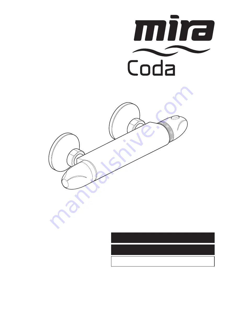
Page 5: ...arise yourself with the part names and to confirm that the parts are included Documentation q 1 x Guarantee Registration Document q 1 x Mira Coda Bar Valve q 2 x Inlet Connectors q 2 x Concealing Plates q 2 x Wall Mounting Brackets q 2 x Washers Filters ...
Page 6: ...ort periods without damage However for safety reasons it is recommended that the maximum hot water temperature is limited to 65 C Minimum Differential between Hot Supply and Outlet Temperature 10 C Cold Water Range 5 C 25 C Thermostatic Shut down For safety the thermostat will shut off the hot supply within 2 Seconds if the cold supply fails achieved only if the hot supply temperature is greater t...
Page 7: ...7 Dimensions 150 24 100 80 70 All dimensions in mm 115 Min to Wall 100 Min to Wall ...
Page 8: ...p twin impeller The pump must be installed on the floor next to the hot water cylinder General Installation must be carried out in accordance with these instructions and must be conducted by designated qualified and competent personnel The installation must comply with the Water Supply Regulations 1999 Water Fittings or any particular regulations and practices specified by the local water company ...
Page 9: ...xer The position of the mixer and the shower fittings must provide a minimum gap of 25 mm between the spill over level of the shower tray bath and the handset refer to illustration This is to prevent back siphonage Note Only use shower fittings recommended by the manufacturer or supplier ...
Page 10: ...suitable thread sealant not supplied and attach the offset connectors to the pipework in the wall The offset connectors must protrude between 35 and 40 mm from the finished wall Note Connections are Hot Left Cold Right This is very important as this product does not allow for reversed inlets 3 Tighten the offset connectors using a spanner on the spanner flats Make sure that the connectors are leve...
Page 11: ... and attach to the offset connectors Note Connections are Hot Left Cold Right 6 Tighten the connections using a suitable spanner 7 Install the shower fittings refer to your shower fittings installation and user guide Sealing Washer Filter 8 Turn on the hot and cold water supplies and check for leaks 9 Before using the shower refer to section Commissioning ...
Page 12: ...s Wall Mounting Bracket Wall Offset Connector Boss Spirit Level 150 mm Apply Silicone Sealant 3 The mounting bracket must extend in the same direction as the offset of the offset connector The angle between the offset connector and the mounting bracket must be less than 45 otherwise the mounting bracket will not fit under the concealing plate 1 Install the pipework make sure that it is set at the ...
Page 13: ...o the offset connectors until they come into contact with the wall Spanner Flats Concealing Plates 9 Caution Make sure that the supply pipework is flushed before installing the bar valve Assemble the bar valve with a sealing washer filter in each inlet and attach to the offset connectors Note Connections are Hot Left Cold Right 10 Tighten the connection using a 20 mm spanner 11 Install the shower ...
Page 14: ...hower outlet is hot enough 2 If not depress the override button and carefully rotate towards position 9 If the water temperature is still not hot enough complete the following procedure 3 Rotate the temperature selector knob back to position 7 4 Using a suitable screwdriver carefully pry off the concealing cap and unscrew the fixing screw 5 Pull off the temperature selector knob without disturbing...
Page 15: ...ting the Temperature The temperature is controlled by rotating the temperature selector knob For safety reasons the temperature is limited by an override stop To obtain a higher temperature press the override button on the temperature selector knob and continue to rotate the knob Adjusting the Flow The flow is controlled by rotating the flow selector knob ...
Page 16: ...eters refer to sections Specifications and Commissioning Fluctuating or reduced flow Check the shower handset hose and filters for any blockage Make sure that the maintained inlet pressures are nominally balanced and sufficient refer to section Specifications Make sure that the inlet temperature differentials are sufficient refer to section Specifications Air lock or partial blockage in the pipewo...
Page 17: ...ted in the thermostatic bar valve body and are accessible through the inlet connectors Caution Make sure that the non return valves are installed correctly to prevent crossflow or malfunction of the valve 1 With the water supplies turned off and the thermostatic bar valve removed remove the sealing washer filter 2 Unscrew the non return valve housing using a 12 mm hexagonal wrench 3 Carefully remo...
Page 18: ...47 Flow Knob Assembly 1630 049 Filter Washer x2 1630 048 Outlet Connector 1663 117 Flow Cartridge 1630 041 Offset Connector Kt x2 1663 113 Non Return Valve x2 1630 054 Temperature Stop Assembly 1663 114 Thermostatic Cartridge 456 29 Wall Mounting Bracket x2 ...
Page 19: ...19 Notes ...
Page 20: ...mprehensive After Sales service As part of our quality and training programme calls may be recorded or monitored Our Customer Services Team is comprehensively trained to provide every assistance you may need help and advice spare parts or a service visit Spare Parts We maintain an extensive stock of spares and aim to provide support throughout the product s expected life Spares can be purchased fr...