


54
9. Communication
This chapter describes:
Communication ports (RS-232 and USB)
Network Management Card (Optional)
UPS Management Software
REPO
9.1 RS-232 and USB Communication Ports
To establish communication between the UPS and a computer, connect
your computer to one of the UPS communication ports using an
appropriate communication cable.
When the communication cable is installed, power management
software can exchange data with the UPS. The software polls the UPS
for detailed information on the status of the power environment. If a
power emergency occurs, the software initiates the saving of all data
and an orderly shutdown of the equipment.
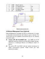
The cable pins for the RS-232 communication port are identified in figure
26, and the pin functions are described in Table 3.
Figure 28. RS-232 Communication Port (DB-9 Connector)
Table 3 RS-232 Communication Port Pin Assignment
Pin
Number
Signal
Name
Function
Direction from
the UPS
1
DCD
Battery Low signal
Out
2
RxD
Transmit to external device
Out
3
TxD
Receive from external device
In
4
DTR
PnP from external device
In
Summary of Contents for 6-10KVA Tower
Page 1: ...USER MANUAL ONLINE UPS 6 10KVA Rack Tower ...
Page 24: ...21 Frequency converter without Bypass AC input ...
Page 31: ...28 Figure 26 Parallel systerm wiring diagram of 6K 10K ...
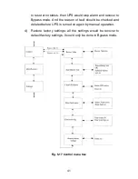
Page 40: ...37 Fig 5 14 Main menu tree ...
Page 47: ...44 Example set rated output voltage value Fig 5 22 Set rated output voltage value ...
Page 61: ...58 614 08090 00 ...