background image

FHD PTZ Camera 

 User Manual 


18 


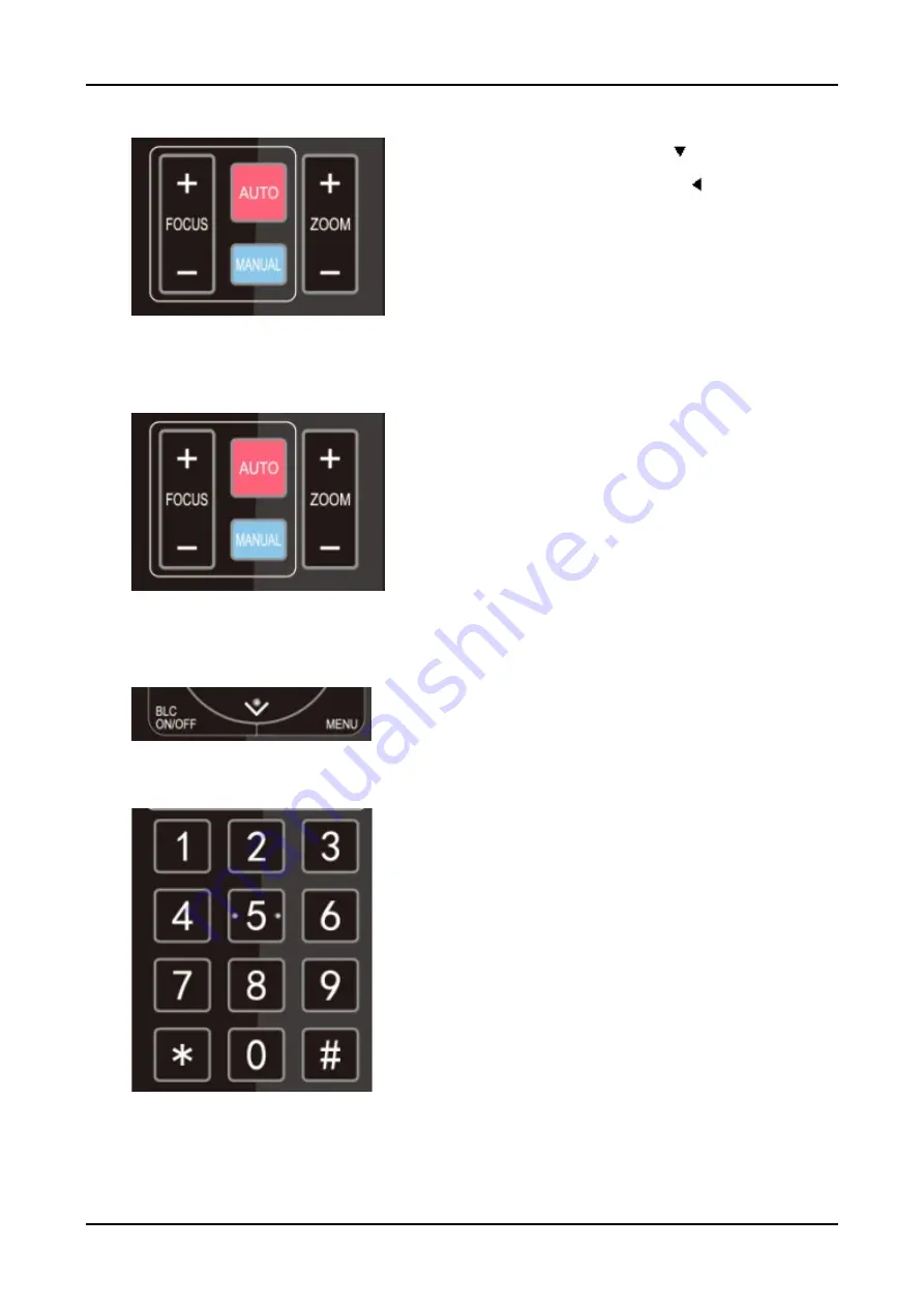
ZOOM IN: press “ZOOM  “ key 
ZOOM OUT: press “ZOOM  ” key 
Press and hold the key, the camera will keep 
zooming in or zooming out and stops as soon 
as the key is released. 
 

4) Focus Control 


Focus (near):Press “

focus+

” key (Valid only 

in manual focus mode) 
Focus (far): Press “

focus-

”key (Valid only in 

manual focus mode) 
Auto Focus: Support 
Manual Focus: Support 
Press and hold the key, the action of focus will 
keep continue and stops as soon as the key is 
released. 

5) BLC Setting 


BLC ON / OFF: support


6

Presets Setting, Running, Clearing 


Preset setting: to set a preset position, the 
users should press the “

SET PRESET

” key 

first and then press the number key 0-9 to set 
a relative preset, 
Note: 10 preset positions in total are available 
by remote controller. 
 
Preset Running: Press a number key 0-9 
directly to run a relative preset. 
Note: Action in vain if a relative preset position 
is not existed. 
 

Summary of Contents for UV950A

Page 1: ...HD PTZ Camera User Manual V1 0 Universal Camera...

Page 2: ...ual is about PTZ camera operation Graphic Symbols Description of graphic symbols used in this manual Symbols Description This symbol indicates that the words are clarification or supplement to this ar...

Page 3: ...the camera If the camera is very dirty clean it with diluted neutral detergent do not use any type of solvents which may damage the surface Electrical Safety Installation and use of this product must...

Page 4: ...Manual iii Magnetic Interference Electromagnetic fields at specific frequencies may affect the video image This product is Class A It may cause radio interference in household application Appropriate...

Page 5: ...Bracket 3 1 4 1 Steps of Wall Mount 3 1 4 2 Steps of Ceiling Mount 4 Product Overview 5 2 1 Product Overview 5 2 1 1 Product Dimension 5 2 1 2 Accessory 5 2 2 Product Feature 6 2 3 Technical Specific...

Page 6: ...b Login 29 4 2 2 Preview 29 4 2 3 Playback 30 4 2 4 Configuration 30 4 2 5 Local Configuration 31 4 2 6 Audio Configuration 31 4 2 7 Video Configuration 31 4 2 8 Network Configuration 35 4 2 9 System...

Page 7: ...FHD PTZ Camera User Manual vi 6 2 Unqualified Applications 57 6 3 Troubleshooting 57...

Page 8: ...Receiving Light 9 RS232 Out 14 USB2 0 4 Reserved Hole for Bottom Switch 10 RS485 In 15 Network Jacket 5 Tripod Screw Hole 11 Audio In 16 DC12V Power Socket 6 Fixation Hole When using the camera pleas...

Page 9: ...utput a Network connection Shown as diagram 1 1 15 b Log in You can reach the Web Interface by typing in the camera s IP address default 192 168 5 163 into a web browser To log in type in admin into t...

Page 10: ...ra User Manual 3 1 4 Bracket Bracket can only be wall mounted or upside down mounted on template and concrete wall but can not be installed on plasterboard 1 4 1 Steps of Wall Mount Figure1 2 Steps of...

Page 11: ...FHD PTZ Camera User Manual 4 1 4 2 Steps of Ceiling Mount Figure1 3 Steps of Ceiling Mount...

Page 12: ...1 1 Product Dimension Figure1 4 Product Dimension 2 1 2 Accessory When you unpack your package check that all the supplied accessories are included Supplied Accessory Supplied Power adapter RS232 cab...

Page 13: ...and stably Low Noise High SNR Low noise CMOS effectively ensure the camera s ultra high SNR 2D 3D noise reduction technology furtherly reduce the noise without image comprising Multi Video Outputs Sup...

Page 14: ...rol and wireless remote control Wide application Applied in remote education lecture recording video conference online training and tele medicine 2 3 Technical Specification Camera Lens Parameter Para...

Page 15: ...n auto flip off BW Mode Gamma Curve Electronic Zoom DCI Lens Distortion Calibration SNR 55dB Interface Parameter Interface Parameter Interfaces HDMI SDI LAN Support POE USB2 0 A IN RS232 IN RS232 OUT...

Page 16: ...ation Protocol UVC Video Communication Protocol UAC Audio Communication Protocol Power Supply HEC3800 Power Socket DC12V Power Adapter Input AC110V AC220V Output DC12V 1 5A Input Voltage DC12V 10 Inpu...

Page 17: ...232 Cable Remote Control User Manual Optional Accessory Mounting Bracket 2 4 Interface Introduction 2 4 1 Interface Diagram The interfaces of this product include HDMI interface USB2 0 interface SDI i...

Page 18: ...2 RS 232 1 RS 232 Diagram Connecting method to PC or controller Device WindowsDB 9 1 DTR 1 DCD 2 DSR 2 RXD 3 TXD 3 TXD 4 GND 4 DTR 5 RXD 5 GND 6 GND 6 DSR 7 IR OUT 7 RTS 8 NC 8 CTS 9 RI Figure1 6 RS...

Page 19: ...XD Transmit Data 4 GND System Ground 5 RXD Receive Data 6 GND System Ground 7 IR OUT IR Commander Signal IR 8 NC No Connection RS232 DB9 Terminal Port Definition NO Terminal Port Definition NO Termina...

Page 20: ...terface you can cascade as above method 2 4 3 Rotary Dial Corresponding video format to 0 F rotary dial 0 Video Format 1080P60 8 Video Format 1080P59 94 1 Video Format 1080P50 9 Video Format 1080I59 9...

Page 21: ...remote controller key combination 2 SDI HDMI Output Connect the monitor with the corresponding video output interface 3 USB2 0 Output Connect this product with computer USB2 0 interface open the Devi...

Page 22: ...Wake Up If there is no operation in the working state it will immediately enter the sleep mode and press any key to wake up 3 2 1 IR Remote Control 1 Standby Key After 3S long press the camera will st...

Page 23: ...Open or close the OSD menu Enter exit the OSD menu or return to the previous menu 11 Camera IR Remote Control Address Setting F1 Camera Address No 1 F2 Camera Address No 2 F3 Camera Address No 3 F4 Ca...

Page 24: ...ng and running preset positions via the IR remote controller Key Instruction 1 In this instruction press the key means a click rather than a long press and a special note will be given if a long press...

Page 25: ...nual Focus Support Press and hold the key the action of focus will keep continue and stops as soon as the key is released 5 BLC Setting BLC ON OFF support 6 Presets Setting Running Clearing Preset set...

Page 26: ...No 1 F2 Camera Address No 2 F3 Camera Address No 3 F4 Camera Address No 4 3 3 Menu Setting 3 3 1 Main Menu In normal working mode press MENU key to display the menu using scroll arrow to point at or...

Page 27: ...e the pointer to the Setup in the Main Menu click the HOME key and enter into the System Setting as shown below PROTOCOL VISCA Pelco P Pelco D Auto Visca ADDR VISCA 1 7 Pelco P 1 255 Pelco D 1 255 Vis...

Page 28: ...RE SET as follow Mode Auto Manual Shutter priority Iris priority and Brightness priority EV On Off only available in auto mode Compensation Level 7 7 only available in auto mode when EV is ON BLC ON O...

Page 29: ...LOR in the Main Menu click the HOME and enter the COLOR SET as follow WBMode Auto Manual One Push 3000K 3500K 4000K 4500K 5000K 5500K 6000K 6500K 70000K Red Tuning 10 10 only available in Manual mode...

Page 30: ...ns On Off DCI Dynamic Contrast Off 1 8 Low Light Mode On Off 4 Focus Move the pointer to the FOCUS in the Menu click the HOME and enter the FOCUS as follow Focus Mode Auto manual IMAGE Brightness 7 Co...

Page 31: ...el Close 1 5 3 3 4 P T Z Move the pointer to the P T Z in the Main Menu click the HOME and enter the P T Z as follow Depth of Field Only effective for remote controller On Off When zoom in the Pan Til...

Page 32: ...r the VERSION as follow MCU Version Display MCU version information Camera Version Display camera version information AF Version Display the focus version information 3 3 7 Restore Default Move the po...

Page 33: ...ss of former remoter is not 1 but another one from 2 3 4 the corresponding camera address will restore to 1 when all parameters or system parameters are restored User should change the remoter address...

Page 34: ...below Firstly open the window of Local Area Connection Properties on computer select the Internet protocol version 4 TCP IPv4 as shown by picture on the left Double click or click the property Interne...

Page 35: ...to verify network connection as steps above mentioned after the finish of camera self check If IP is default open DOS command window and input 192 168 5 163 then press Enter key It will show message a...

Page 36: ...t top of the interface display English click English 2 Download Plug in When first using IE browser to access the web conferencing camera the login page will appear Playback plug in is not installed p...

Page 37: ...earch and search out the video file click Play to play the image file 4 2 4 Configuration Click Configuration to enter into the device parameters setting page There are the following options Local con...

Page 38: ...mpling Frequency Set sampling frequency and manually reboot the device after change MP3 AAC default 16000 32000 44100 48000 optional G 711A default value is 8000 Sampling Precision Set sampling precis...

Page 39: ...stream 1 150F optional Minimum QP of key frame interval Set minimum QP of key frame interval Default 20 10 51 optional Stream Name When streaming via rtsp or rtmp user can modify stream name Main Stre...

Page 40: ...on default 0 7 to 7 optional BLC Set back light compensation valid when it is auto status default is off Gain Limit Set the gain limits valid in auto focus iris priority and brightness priority Gain S...

Page 41: ...Contrast Set the contrast default 7 0 14 optional Sharpness Set the sharpness value default 6 0 15 optional Gamma Gamma value setting default 0 45 0 50 0 55 0 63 optional Dynamic Contrast Set dynamic...

Page 42: ...tically Adjust According to the Resolution Yes No Main Stream Character Size Set the character size of the display the device will automatically restart after changed default 48 28 200 optional Second...

Page 43: ...ill be valid when display Save successful RTMP access RTMP equipment IP address 1935 live av0 av0 main stream av1 second stream RTMP Access Rtmp equipment IP address 1935 live av0 av0 main stream av1...

Page 44: ...IP Port 5060 Range 0 65535 GB28181 Server Address IP address of the computer Server SIP Port 5060 Range 0 65535 Server ID 34020000002000000001 Click on the Save button it will be valid when display Sa...

Page 45: ...zones optional Time Type Set the time types default 24 hours optional 12 hours Enable NTP Enable disable NTP Update Interval Set the NTP server automatic updated time interval Valid after setting NTP...

Page 46: ...is completed you need to restore the factory default values a restore the factory default through web configuration b restore the factory default value through the menu c remote control shortcut key 6...

Page 47: ...osition and then pulled back after that self test is completed 5 1 VISCA Protocol List 5 1 1 VISCA Protocol List Ack Completion Message Command packet Remark ACK z0 41 FF Returned when the command is...

Page 48: ...mmand canot be executed due to current conditions For example when commands controlling the focus manually are received during auto focus 5 1 2 Camera Control Command Command Function Command Packet R...

Page 49: ...Focus Direct 8x 01 04 47 0p 0q 0r 0s 0t 0u 0v 0w FF pqrs Zoom Position tuvw Focus Position CAM_AF Sensitivity High 8x 01 04 58 01 FF Focus sensitivity Setting Normal 8x 01 04 58 02 FF Low 8x 01 04 58...

Page 50: ...Sensitivity Setting Normal 8x 01 04 A9 01 FF High 8x 01 04 A9 02 FF CAM _RGain Reset 8x 01 04 03 00 FF Manual Control of R Gain Up 8x 01 04 03 02 FF Down 8x 01 04 03 03 FF Direct 8x 01 04 43 00 00 0p...

Page 51: ...8x 01 04 0B 02 FF Down 8x 01 04 0B 03 FF Direct 8x 01 04 4B 00 00 0p 0q FF pq Iris Position CAM_Gain Limit Reset 8x 01 04 0C 00 FF Gain Limit Setting Up 8x 01 04 0C 02 FF Down 8x 01 04 0C 03 FF Gain...

Page 52: ...0 0p FF p WDR Level Positon CAM_NR 2D 8x 01 04 53 0p FF P 0 7 0 OFF 3D 8x 01 04 54 0p FF P 0 8 0 OFF CAM_Gamm a 8x 01 04 5B 0p FF p 0 4 0 Default 1 0 45 2 0 50 3 0 55 4 0 63 CAM_Low Li ght Mode ON 8x...

Page 53: ...e verse On 8x 01 04 61 02 FF Image Flip Horizontal ON OFF Off 8x 01 04 61 03 FF CAM_Picture Flip On 8x 01 04 66 02 FF Image Flip Vertical ON OFF Off 8x 01 04 66 03 FF CAM_ColorS aturation Direct 8x 01...

Page 54: ...Flip H 8x 01 04 A4 01 FF Flip V 8x 01 04 A4 02 FF Flip HV 8x 01 04 A4 03 FF CAM_VideoS ystem Set Camera video system 8x 01 06 35 00 0p FF P 0 E Video format Pan_tiltDrive Up 8x 01 06 01 VV WW 03 01 F...

Page 55: ...06 05 FF Pan tiltLimitS et Set 8x 01 06 07 00 0W 0Y 0Y 0Y 0Y 0Z 0Z 0Z 0Z FF W 1 UpRight 0 DownLeft YYYY Pan Limit Position TBD ZZZZ Tilt Limit Position TBD Clear 8x 01 06 07 01 0W 07 0F 0F 0F 07 0F 0F...

Page 56: ...ormal y0 50 03 FF Low CAM_AFZone Inq 8x 09 04 AA FF y0 50 00 FF Front y0 50 01 FF Beting y0 50 02 FF Meeting y0 50 03 FF Education y0 50 04 FF Moving y0 50 05 FF Middle CAM_WBMod eInq 8x 09 04 35 FF y...

Page 57: ...50 0B FF Iris priority y0 50 0D FF Bright CAM_Shutter PosInq 8x 09 04 4A FF y0 50 00 00 0p 0q FF pq Shutter Position CAM_IrisPosI nq 8x 09 04 4B FF y0 50 00 00 0p 0q FF pq Iris Position CAM_Gain Limit...

Page 58: ...B W CAM_Memory Inq 8x 09 04 3F FF y0 50 0p FF p Memory number last operated SYS_MenuMo deInq 8x 09 06 06 FF y0 50 02 FF On y0 50 03 FF Off CAM_LR_Rev erseInq 8x 09 04 61 FF y0 50 02 FF On y0 50 03 FF...

Page 59: ...CAM_Gamma Inq 8x 09 04 5B FF y0 50 0p FF p Gamma setting CAM_VersionI nq 8x 09 00 02 FF y0 50 ab cd mn pq rs tu vw FF ab cd vender ID 0220 mn pq model ID rs tu ARM Version vw reserve VideoSystemI nq...

Page 60: ...e7 Up 0xFF Address 0x00 0x08 Pan Speed Tilt Speed SUM Down 0xFF Address 0x00 0x10 Pan Speed Tilt Speed SUM Left 0xFF Address 0x00 0x04 Pan Speed Tilt Speed SUM Right 0xFF Address 0x00 0x02 Pan Speed T...

Page 61: ...sponse 0xFF Address 0x00 0x59 Value High Byte Value Low Byte SUM Query Tilt Position 0xFF Address 0x00 0x53 0x00 0x00 SUM Query Tilt Position Response 0xFF Address 0x00 0x5B Value High Byte Value Low...

Page 62: ...0x20 0x00 0x00 0xAF XOR Zoom Out 0xA0 Address 0x00 0x40 0x00 0x00 0xAF XOR Stop 0xA0 Address 0x00 0x00 0x00 0x00 0xAF XOR Focus Far 0xA0 Address 0x01 0x00 0x00 0x00 0xAF XOR Focus Near 0xA0 Address 0...

Page 63: ...lt Position Response 0xA0 Address 0x00 0x5B Value High Byte Value Low Byte 0xAF XOR Query Zoom Position 0xA0 Address 0x00 0x55 0x00 0x00 0xAF XOR Query Zoom Position Response 0xA0 Address 0x00 0x5D Va...

Page 64: ...age may flicker Do not operate close to powerful electromagnetic radiation such as TV or radio transmitters etc 6 3 Troubleshooting No image 1 Check whether the power cord is connected voltage is OK P...

Page 65: ...teady horizontal and level surface 2 Check the building and any supporting furniture for vibration Ceiling mounts are often affected by building vibration more than wall mounts 3 Any external vibratio...

Page 66: ...inrray Industry Co Ltd may not be cloned copied or translated in any way without the explicit permission of the company Product specifications and information referred to in this document are for refe...

Reviews: