4.
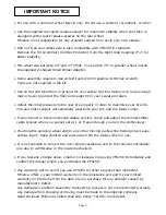
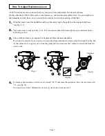
Place your rear wheel in between the couplings.
1)
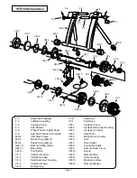
Turn the Wheel Position Adjust Knob (F-8) counter-clockwise to
retract the Left Side Coupling (F-2). (see Fig. C)
2)
Turn the Hub Handle (F-7) counter-clockwise to almost fully
retract the Right Side Coupling. (see Fig. D)
(Fig. C)
(Fig. D)
(Fig. E)
3)
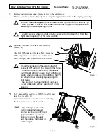
Insert the left side (quick lever side) skewer into the Left Side
Coupling (F-2) first.
The quick lever shaft must be inserted into the cut-out on the
coupling snugly to hold the bike stable. Turn the coupling to adjust
the cut-out position. (Fig. F)
4)
While keeping this position, slowly come down the bike to align
the right side acorn nut to the Right Side Coupling (F-1).
5)
Tgihten the Hub Handle clockwise to clamp the rear wheel.
Turn 2 more rotations after you feel resistance and you see the
frame starts opening slightly.
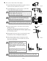
Both left and right side couplings are
designed to suit the supplied quick release
skewer. Esepcially, the left side coupling
must fit perfectly in the skewer head to get
correct stability.
Any skewer type which lever is located on
the end of the axle (Fig. G) or the lever will
not be bent over right angle (Fig. H) cannot
be used on VFS150.
!
(Fig. F)
(Fig. H)
!
Too tight setting will cause damage to both VFS150 and your bike frame.
Too loose setting may cause the bike to come out of the trainer during use.
- Page 5 -
!
The tire must be away from any plastic part and touches
the Drive Roller only. (see Fig. E)
Turn the Wheel Position Adjust Knob (F-8) to locate the
tire in the center of the Drive Roller.
X
(Fig. G)
!
Do not use Wheel Position Adjust Knob for clamping the
hub axle. It must be done by the Hub Handle (F-7) only.
!
Do not over-loosen the Hub Handle, otherwise the
inside nut will have to be loosened and you cannot
clamp the hub axle with proper torque.


