


n
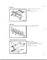
Note: When disassembling/ reassembling the Transfer Unit, High Voltage Unit, Registration
.
Roller Assy. and Paper Take-up Roller Unit, please note
each has a peg that fits into
a hole in the
Frame and a screw that secures the unit in the Left Frame.
Release each unit from the Drive Unit
when removing the unit.
Image Transfer Unit
Inter-face Plate Image Transfer Unit
Left Frame
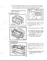
High Voltage Unit
High Voltage Unit
1. Remove the Outer Cover. (Refer to sect. 1)
2.
Remove the Fusing Unit. (Refer to sect. 2-2)
3. Remove
Rear Frame. (6 screws, 1
connector)
4. Remove
Image Transfer Unit. (1
Note: With the Left Frame open, release
the Transfer Unit. Pulling the Transfer
Unit in the direction indicated by
the
arrow, remove it.
Note: Don’t touch the surface of the
Transfer Roller with the hand.
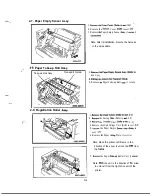
1. Remove the Outer Cover. (Refer to sect. 1)
2.
Remove
Fusing Unit. (Refer to sect. 2-2)
3.
Remove the Transfer Unit. (Refer to sect. 2-
3)
4.
Remove the
Voltage Unit. (1 screw, 1
Note: Pulling the High Voltage Unit in the
direction indicated by the arrow,
remove it.
D-6
Summary of Contents for 2060
Page 1: ......
Page 2: ......
Page 3: ...S P A 3 1 0 Service Parts Manual September 1996 Revision C 02 ...
Page 4: ......
Page 5: ...WARNING LABELS i ...
Page 31: ... I PRINTING PROCESS I 9 Paper Exit Duplex I Sensor C l ...
Page 51: ...E ADJUSTMENT 1 IMAGE REGISTRATION E 1 ...
Page 52: ... ...
Page 57: ......
Page 61: ......
Page 64: ... 0993 PARTS MANUAL MINOLTA QMS ...
Page 68: ...L H O U S I N G 9C 3 PARTS MANUAL ...
Page 70: ...FRAMES 7 L J P PARTS MANUAL ...
Page 72: ...1 PARTS MANUAL1 5 ...
Page 76: ......
Page 78: ...T R A N S P O R T SFCTION 2 9 E PARTS MANUAL L ...
Page 79: ......
Page 80: ......
Page 81: ......
Page 82: ......
Page 83: ......
Page 84: ...0 a P A R T S M A N U A L ...
Page 86: ... 4 ...
Page 87: ... ...
Page 88: ......
Page 92: ......
Page 93: ... ...
Page 94: ......


