background image


13


TILTING THE TABLE, ADJUSTING THE MITER GAUGE, 
FENCE, AND THROAT PLATE 

TABLE TILTING 

The bandsaw table will tilt up to 45 degrees. To tilt the table loosen the large bolt 
enough for the table to slide in both trunions in the table tilt scale and adjust tilt 
by hand (SEE FIGURE 26 TRUNNION BOLT).  Tighten the bolt. Note that if the 
lower guide assembly has been positioned close to the bottom of the table it will 
be necessary to move this guide assembly down in order to tilt the table more 
than 10 degrees.  On some machines, if the bolt is only partially loosened,  the 

left  trunnion tends to bind a bit. 

You can tilt about 8-10 degrees in 

the opposite direction by removing  

the zero degree positive stop at 

the rear underside of the table.(SEE 

FIGURE 

27, 

POSITIVE STOP BOLT) . This 

may be desirable for such 

operations as cutting Bandsawn 

dovetails where the ability to tilt in 

both directions is useful.  
 On some saws, the tilt mechanism trunnions are very tight. This can be eased 
by removing the table and using some very fine valve grinding(abrasive) 
compound to loosen the sliding action of the trunnion. Valve grinding compound 

Summary of Contents for MM 16

Page 1: ...HOOTING 15 THE SIX RULES OF SAWING 16 SPARE PARTS LISTS AND ILLUSTRATIONS 21 RESOURCE RECOMMENDATIONS 33 Note This manual has been assembled by Art Liebeskind from information and invaluable help from Bill Sams Carl Knapp Erik Delaney and many hints from others on the MiniMax Forum Users Group Please use care and discretion and realize that all adjustments and operations are done at your own risk ...

Page 2: ...llet jack a forklift if you are fortunate enough to have the use of one or the unit may be lifted and moved by a hoist connected to the lift holes at the top of the saw See Figure 1 Hoist Holes at right Lifting is done by passing a rope through the holes in the top of the machine On completing the operation close the above mentioned holes with the plastic caps provided At any rate in addition to m...

Page 3: ...ut the plastic off the machine and remove it Inside the plastic you will find a black plastic tool kit The tool kit includes a push stick allen wrenches open end wrenches a factory manual and 4 leveling bolts See Figure 3 Tool Kit Use the appropriate metric wrench in your tool kit to remove the two lag bolts that secured your saw to the frame Once you have removed the bolts slide the bandsaw off t...

Page 4: ...e the mobility system it will not be bolted down Another option is to use wooden wedges If the machine is moved even a few inches the floor could change the level With a wooden wedge the short leg can be found and the wedge pushed under a little further to reestablish the level If the machine is going to stay put it is helpful to put rubber pads under the bearing legs Glue a piece of wood to the p...

Page 5: ... an electrician See Figure 7 Electrical Nameplate If you purchased a single phase machine all MM16 s and single phase MM20 s the machine will have 3 wires The yellow green wire is the ground and the other two are your hot wires It does not have or use a neutral wire If your machine is 3 phase and the machine is running backwards disconnect the power and switch two of the hot legs The MM16 has a sh...

Page 6: ...onnect adaptor flange 4 flex hose to 100mm available from Onieda Air Systems see sources Depending on the particular hose or parts you get it may be necessary to use a rubber plumbing connector 4 with two hose clamps to adapt your hose or the quick disconnect to the outlet A replaceable plywood deflector below the lower guides helps direct the dust to the port See Figure 11 Dust Deflector CFM Requ...

Page 7: ...ur sources section GUIDE INSPECTION AND ADJUSTMENT The guides are European ball bearing type For very narrow width blades MiniMax is developing a cool block guide system for using 1 8 and smaller blades LOWER GUIDES On the MM16 or MM20 remove the lower guides See Figure12 Lower Guides This is a good chance to check to see if the guides are cleaned of the Cosmoline Loosen the allen screws in the ba...

Page 8: ...otruding beyond outside edge of tires teeth should point downward toward table if not turn blade inside out 6 Adjust tension 7 Adjust tracking by spinning wheel manually to check tracking and blade location 8 Check that the plane of the top and bottom wheels are in the same plane Coplanar see Coplanar section Note that many experts insist that this is not an issue with flat tires such as those on ...

Page 9: ... tighten the lock As the lock ring tightens turn the guide adjustment with it to cinch it down securely Now spin the guide You should barely feel it touch the blade 11 Close doors and reinstall plastic blade guard 12 Rotate blade by hand to check tracking 13 Plug in saw turn power on to check operation ADJUSTMENTS TENSIONING BLADE TRACKING SQUARING BLADE TO TABLE ADJUSTMENTS Tuning and tweaking a ...

Page 10: ...om 15 000 to 30 000 psi Once you find the proper tension for the blade s you use you can create your own indicator marks lines for repeatability A good recommendation is to use different colored markers and color code the different blade widths TRACKING You can not track a blade until the proper tension has been set Pay careful attention to the preceding section on proper tensioning of the blade T...

Page 11: ...eel Forward Top closer to the door loosen the top and tighten the bottom Again rotate the wheels in reverse to check where the blade end up Once the lower blade is tracking to your satisfaction lock the hub bolt again SQUARING BLADE TO TABLE SIDE TO SIDE SQUARENESS After all tracking and tensioning of the blade is accomplished check the blade for table squareness Use a simple machinists square If ...

Page 12: ...y See Figure 22 GUIDE POST ADJUSTMENT When re positioning the height of the upper guide assembly to be close to the height of the material to be cut the guide bearing adjustments made earlier should stay in position and in line with the blade If not loosen the two center bolts See Figure 23 UPPER GUIDE POST ALIGNMENT behind the locking knob and move lightly by hand until the bearings remain in lin...

Page 13: ...UST THE PLANES OF THE WHEEL COPLANAR 1 Prepare a 3 4 plywood template approximately 10 wide by 67 long with one edge perfectly straight 2 Cut an arc out of the template to bypass table or remove table Cut notches as needed to bypass the wheel hubs and the saw frame 3 With your widest blade on and fully tensioned hold the template against the face of the upper and lower wheels If the wheels are cop...

Page 14: ... order to tilt the table more than 10 degrees On some machines if the bolt is only partially loosened the left trunnion tends to bind a bit You can tilt about 8 10 degrees in the opposite direction by removing the zero degree positive stop at the rear underside of the table SEE FIGURE 27 POSITIVE STOP BOLT This may be desirable for such operations as cutting Bandsawn dovetails where the ability to...

Page 15: ...ing parallel to the fence Every blade will cut in a slightly different manner and you may have to adjust the fence angle to compensate for this drift To check blade drift mark a straight line on a board 24 long rip the board freehand while carefully following the line About halfway through the cut stop the saw and leave the board in place Mark the side of the board on the saw table with a soft pen...

Page 16: ...affin blade lube to ease cutting and reduce pitch build up Spray PAM works well Check bearings for sawdust buildup to prevent damage to bearings Keep holes in table insert clear for effective dust collection Always remove tension from blade at the end of day establish a signal such as a ribbon to hang from the door as a reminder to retension before starting the saw TROUBLE SHOOTING CHART THE PROBL...

Page 17: ...estricted in any lateral movement Make sure tire surfaces are in good condition they cannot be hard flattened out cracked or brittle On mills with loose fitting V belts replace them with the next size down so they are tight fitting This will eliminate over 80 of the vibration in your mill and the blade Mount the blade on the machine and apply the tension to the band that the manufacturer recommend...

Page 18: ...For the woodworker using 1 and 1 1 4 bands not only is water unacceptable as a lubricant but it also rusts the bands causing deep pitting and inappropriate chip swelling This prematurely destroys the body of the band and its gullets It also dry rots your tires or V belts For proper lubrication mix HIGH ADHESION CHAIN SAW BAR OIL with 50 kerosene or diesel fuel Apply the solution with a spray bottl...

Page 19: ...SET Appropriate set is when you have a mixture of 65 70 saw dust and 30 35 air in the space between the body of the band and the wood you are cutting The SIGN you are looking for when you are running appropriate set IS A GOOD 80 85 SAW DUST EJECTION FROM THE CUT If you are running too much set for the mass or thickness of the wood you have too much air and not enough saw dust You will leave EXCESS...

Page 20: ...he pitch you will achieve straight grade cuts every time YOU MUST UNDERSTAND APPROPRIATE SET AND HOOK ARTICULATION THEY WORK TOGETHER We manufacture for North America 5 appropriate sets with a 10 degree hook angle 70 of the time this hook angle will be perfect for whatever you are cutting WARNING Again just as I have brought to your attention the short life of a dial indicator you are also trustin...

Page 21: ...is causes the saw dust to be sucked out of the cut The saw dust effectively cools the gullet by spinning around the inside and spilling over the back side of the next tooth You MUST maintain a 40 gullet fill for proper cooling and extended cutting time If you sharpen just the face and the back side of the tooth you ruin the gullet integrity and destroy the performance of the band THERE ARE 4 PARTS...

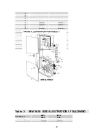
Page 22: ...ely essential to keep meticulously to the following procedures 1 Indicate the model and part number of the machine 2 Indicate the table code and reference number of the parts required 3 Indicate the quantity required Table 1 MM 16 20 SEE ILLUSTRATION 1 FOLLOWING Reference MM 16 CODE MM20 CODE 1 43040026 43050025 2 43040001 43050001 3 4 05061916 05061916 5 6 43040038 43040038 7 8 9 10140007 1014000...

Page 23: ...6 43052024 39 40 30101900 30101900 41 48178212 48178212 42 30070700 30070700 Table 1 CONTINUED MM 16 20 SEE ILLUSTRATION 1 FOLLOWING 43 44 45 46 47 48 Table 3 MM 16 20 SEE ILLUSTRATION 3 FOLLOWING REFERENCE MM 16 CODE MM 20 CODE 1 2 48132400 48022300 ...

Page 24: ...1 48130700 48020900 22 48131100 48140200 23 10011270 10140027 24 10160000 10160000 25 26 10044951 10044951 27 48097100 48097100 28 29 48132400 48022300 30 12010103 12010105 31 01080102 01020102 32 48132200 48011800 33 48138000 48149300 34 48132800 48012800 35 43040042 43060032 36 43040040 43060031 37 48132400 48022300 38 39 03190303 03190304 40 43040045 43040045 41 42 43 44 04114007 04115002 1 ph ...

Page 25: ...24 ...

Page 26: ...040060 43040060 7 10066763 10066763 8 43040043 43050029 9 48132000 48132000 10 48132100 48132100 11 12 13 14 15 16 17 18 43040062 43040062 19 20 21 22 23 24 25 26 27 28 29 43040053 43040053 30 31 32 33 34 43040028 43040028 35 10230000 10230000 36 43040061 43040061 37 43040052 43050026 38 43040057 43070129 39 43050024 40 41 42 43 ...

Page 27: ...26 ...

Page 28: ...427171 2 30141000 30141000 3 48152401 48152400 4 01210405 01210405 5 6 48152400 48152400 7 43070132 43070132 8 9 48152200 48152200 10 11 43040030 K 43060027K 12 13 14 15 16 43040030 43060027 17 43070131 43070131 18 19 20 21 22 10140028 10140028 23 43060043 40070026 24 25 43070231 43070231 26 27 ...

Page 29: ...28 ...

Page 30: ... ILLUSTRATION 10 FOLLOWING MM 16 MM20 Ref Nr CODE CODE 1 2 48098801 48098801 3 27090000 27090000 4 30131400 30131400 5 6 48098802 48098802 7 27081500 27081500 8 9 10 48098804 48098804 11 27071300 27071300 12 48132701 48098806 ...

Page 31: ...3050020 2 43040041 43040041 3 15 15 4 17 17 5 12 12 6 43040033 7 43040049 8 43040058 9 43050022 10 48127006 48127006 11 48127011 48127011 12 10040015 10040015 13 Table 12 MM 16 20 SEE ILLUSTRATION 12 FOLLOWING MM 16 MM20 REFERENCE CODE CODE 1 43040034 43060030 2 15 16 3 17 18 4 12 11 5 ...

Page 32: ...31 ...

Page 33: ...32 NOTE THAT PARTS WITHOUT A CODE ARE NORMALLY STOCK FASTENERS OR WASHERS ETC ...

Page 34: ...slicer Blades 1 800 241 6748 TENSION GAUGES Iturra Design Starret Lenox Iturra Blade Gage 1 888 722 7078 Grainger Starret www grainger com DUST COLLECTION SYSTEMS Oneida Air systems 1 800 732 4065 BOOKS The Art of the Bandsaw by Mark Duginske Bandsaw Handbook by Mark Duginske The Bandsaw Book by Lonnie Bird Contact MiniMax user s group www yahoogroups com for user friendly advice and discussions ...

Reviews: