miniDSP Ltd – Hong Kong / Email :
/ Features and specifications subject to change without prior notice
16
3.2
C
ONNECTIONS FOR ACOUSTIC MEASUREMENT
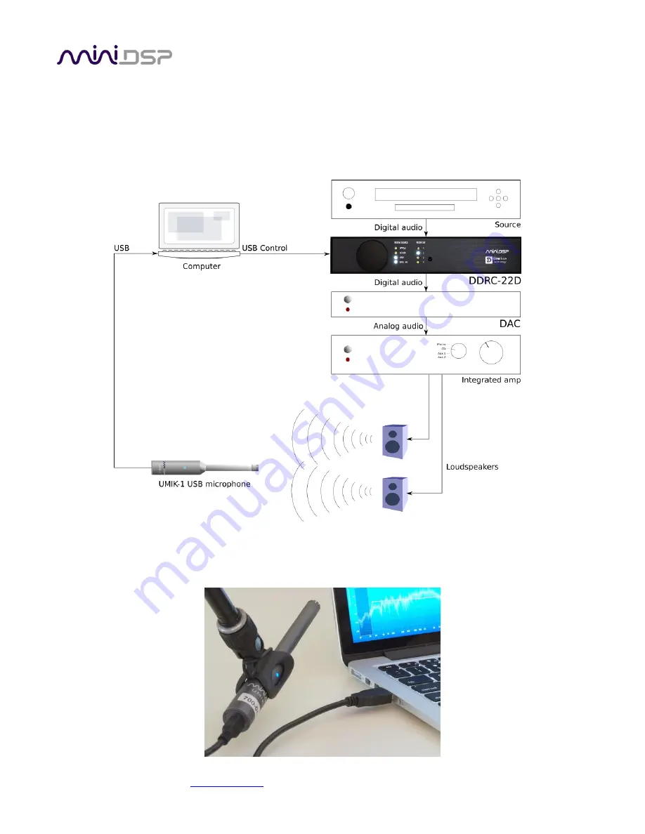
The figure below shows a typical connection diagram for performing acoustic measurement. (This example uses
the DDRC-22D.) No changes to existing audio connections are needed. Simply:
1.
Connect the supplied USB (type A to type B) cable from the processor to a USB port on the computer.
2.
Connect the supplied USB (type A to mini type B) cable from the UMIK-1 to a USB port on the computer.
Place the UMIK-1 microphone into the microphone stand. Position the computer and cabling so that there is
enough freedom of movement to move the microphone into the needed locations.


