background image

Detector Assembly

Detector Assembly

EN

EN

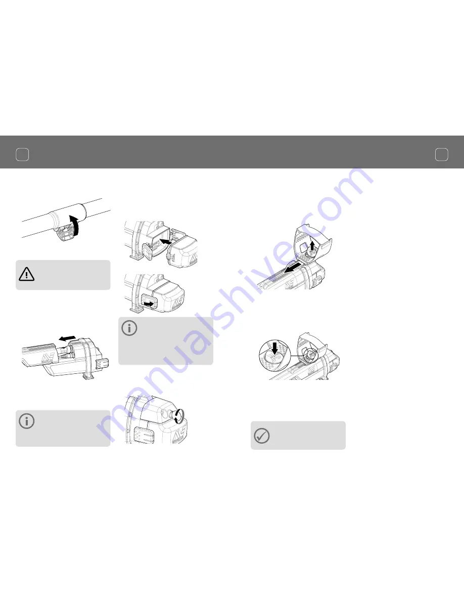
Attach Armrest

1. 

Lift the armrest lock until it is fully open. 
Slide the armrest onto the rail on top of 
the chassis. Ensure that the sloping sides 
of the armrest face toward the control 
panel. 

2. 

Slide the armrest along the rail so that it 
will be positioned comfortably just below 
your elbow when holding the detector.

3. 

Push down the armrest lock to secure the 
armrest in position. 
 

Adjust Armrest Strap

1. 

Undo the hook and loop armrest strap.

2. 

Tighten the strap until your arm is secure 
in the armrest, and fasten.

TIP

To fit a smaller arm, the strap can 
be fitted upside down and passed 
through the armrest three times.

4. 

Lock the camlock by pushing the lever 
towards the shaft. 

Attach control box

WARNING  

PINCH POINTS - CONTROL BOX

Take care when sliding the control 
box onto the chassis.

1. 

Slide the control box partly onto the 
upper shaft. When it reaches half way it 
will click into place to prevent the control 
box from sliding while the connectors are 
fitted.  

2. 

Attach the coil and control panel cables 
to their respective connectors and firmly 
tighten the retaining rings.

NOTE

To optimise performance, the 
retaining rings have fine threads for 

precise fitment. Take care not to cross-thread the 
retaining rings during assembly.

3. 

Slide the control box further along the 
upper shaft until it locks into place. 

Attach battery and headphone module

1. 

Fit the battery pack onto the control box 
and close the latches to secure it in place. 

NOTE

The Lithium-Ion battery pack is 
supplied partially charged and 

should be charged for up to eight hours to 
maximise your first use. See ‘Charging Batteries’ 
for information on how to recharge the 
GPZ 7000 battery.

2. 

Fit the headphone module onto the 
control box. Use a screwdriver or coin to 
gently tighten the bolt, taking care not to 
damage the thread by over-tightening. 

5

4

Summary of Contents for GPZ700

Page 1: ...Getting Started Guide Gu a de Introducci n Guia de Inicia o Guide de d marrage XChange 2 Compatible...

Page 2: ...ight Apart from any use permitted under the Australian Copyright Act 1968 Cth or other applicable laws any unauthorised use appropriation or reproduction of this document or any part of it is strictly...

Page 3: ...ent into an outlet on a circuit different from that to which the receiver is connected Consult the dealer or an experienced radio TV technician for help SOFTWARE Certain components of the XChange2 PC...

Page 4: ...coil and lower shaft to mid shaft 1 Release the camlock on the lower shaft by pulling the lever away from the shaft 2 Thread the coil cable up the centre of the mid shaft 3 Insert the mid shaft into t...

Page 5: ...s 1 Slide the control box partly onto the upper shaft When it reaches half way it will click into place to prevent the control box from sliding while the connectors are fitted 2 Attach the coil and co...

Page 6: ...of the strap through the narrowest slot Pull until the strap is captured by the Flex link 2 Attach the Flex link to the GA 10 shaft Align the holes in the shaft with the key on the Flex link Push the...

Page 7: ...a standard USB port 1 Connect the supplied USB cable to the WM 12 2 Connect the other end of the USB cable to the BC 10 battery charger or directly to a USB port on your PC Connecting Headphones The...

Page 8: ...o detecting for reference Read the instruction manual on CD for more information on advanced operation of the detector Charging Batteries BC 10 Battery Charger WARNING Do not immerse the BC 10 charger...

Page 9: ...t guide sequence to begin detecting there is much more information readily available to help you optimise your detector s performance and learn how to use all of its functions GPZ 7000 Control Panel M...

Page 10: ...a Tel 61 0 8 8238 0888 Email minelab minelab com au Minelab International Ltd Europe Middle East Africa Tel 353 0 21 423 2352 Email minelab minelab ie Minelab Americas Inc North South Central America...

Reviews: